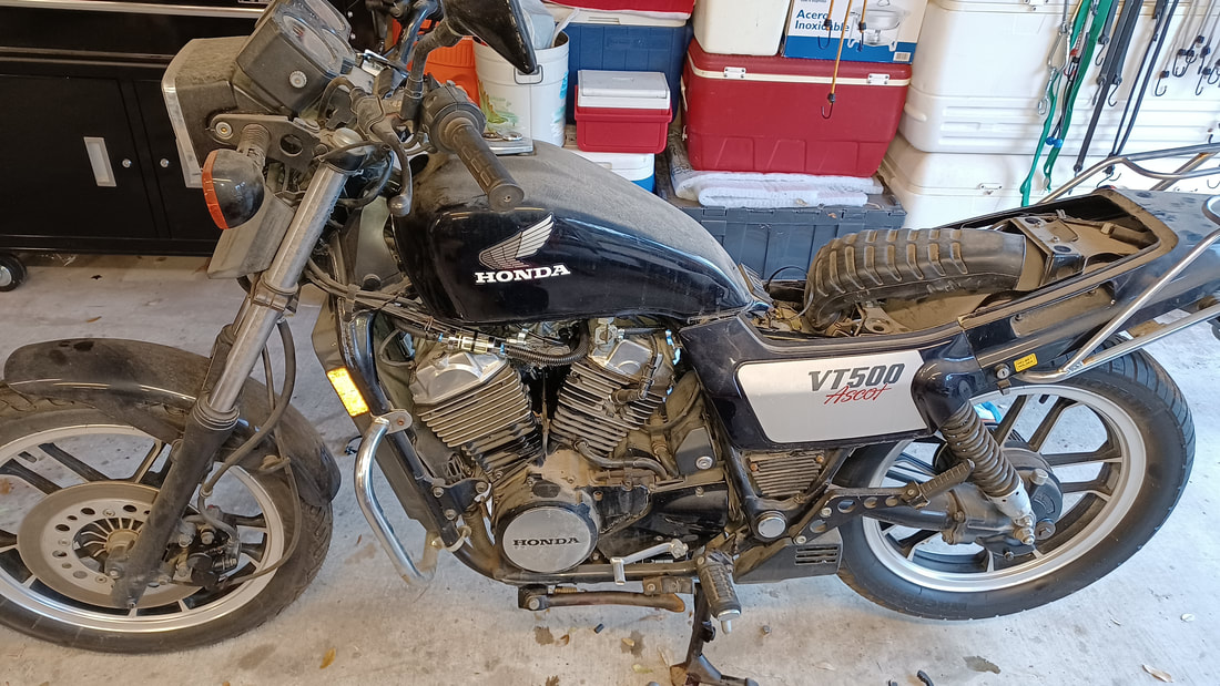
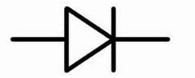
 1984 Honda VT500 Ascot I had never heard of a Honda Ascot when the tow truck dropped this little gem on the driveway. It was, in the early 80's, an absolute technology showcase in a mid-size package. She has a 6-speed transmission, shaft drive, mag wheels, liquid cooling, studs on the rear fame members designed to hang detachable hard bags, and even a warning light on the dash to tell you if your tail light has burned out! Remarkably, they didn't sell worth a darn and were produced only two years. In the end, Honda dealers flushed these bikes onto the market at fire-sale prices. Their only real problem seemed to be that the gas tank was a little to small for a bike that would have made a great lightweight touring bike. Look them up. The more you read about the VT500 Ascot, the more impressed you will be. If you find one as nice as this one, buy it for a song and ride it for the rest of your life. As you can see, this one came in very neglected, but not abused. She had spent too much time sitting lonely in a shed. So naturally the carbs were fouled, the battery was toast, the brake fluid was bad, and she needed an oil change. But what was particularly interesting about this job, was that she was on her way to being in a movie...and needed to run right and right away. Being a Honda, parts were easy to get and with the normal Make-Run project ministrations, she was ready to go right on schedule...but when it came time to change her four spark plugs (two per cylinder), she showed herself to be a true Honda V-Twin. I cannot figure out why so many Honda V-Twins are like this, but I see it over and over, across lots of different models they have made. It is such an odd quirk for a company that usually does everything nearly perfectly, I have just got to tell you about it. On lots of their V-Twins, Honda makes it absurdly difficult to change the front left spark plug. Is this a big deal? No, not really. But it can be really aggravating if you don't have the right spark plug socket. And I have seen a number of bikes come in that have clearly had all of their other plugs changed at some point, but the front left plug has never been changed. Some mechanics just skip it, rather than deal with getting the plug out. That is really crummy. So the message here is, if you have a Honda V-Twin, make sure your mechanic is willing to do the job right. (I guess that is good advice, whatever bike you may have!) You may notice that the photo of the long, thin spark plug socket shows lots of scratch marks on the outside. That is because on some bikes, even this special tool was too thick to fit down the hole. So naturally, I took it over to the bench grinder and ground it even thinner! Sheesh! Well, it all worked out fine in the end, and out little hero got a nice bath and made it to the set on time. The script says the rider finds a dead body in the woods. Who did it? Was it Major Mustard with a wrench? How do you know if your battery charging system is working? Check your battery voltage with the bike turned off. Start the bike. Check the battery voltage with the bike running at 1500 RPM or more. The battery voltage should now be higher that it was...and ought to be somewhere between 13V and 15V. If it is not, and particularly if your battery voltage is LOWER than it was with the bike turned off, your charging system has taken a powder. Now you need to figure out what is wrong with it. 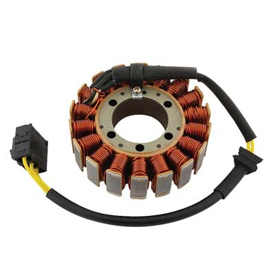 Typical Motorcycle Stator Typical Motorcycle Stator One fun thing about motorcycles is that the charging system (which you would just call "the alternator" on your car) is broken into its two major components, so you can look at them (and repair them) independently. The first part, the Stator (so named, I think, because it STAYS still while magnets spin around it) is simply (usually) three coils of wire that are located very near one or more magnets attached to the engine, so that when it is running, the magnets spin by the coils, inducing an electric current within them. (Yes, Virginia, that is how almost all the electricity you have ever used is made. Coils of wire are passed through a field of magnetic flux, causing the electrons within the wire to get excited and go flying off to some atoms further down the wire that are not quite so excited.) As you can see in this photo, the three coils are artfully arranged so that you would be unlikely to guess that there are three of them, but we know there are three and only three because there are three yellow (typically yellow) wires connected to the lot of them. How that works out will become clearer as we move on... The second part (Have you already forgotten there is a second part? I would have.) is the Regulator. The Regulator, as you might well imagine, regulates the voltage produced by the Stator. Because they are attached to the engine and the engine runs at wildly variable speeds, the magnets induce wildly variable current in the Stator, which is seen as wildly variable voltages on the output connector of the Stator (the three yellow wires). What is worse is that the Stator is producing AC current (alternating current) while your motorcycle, and notably your motorcycle battery, operates on DC current (direct [unidirectional] current). So when we call that second part of the charging system "the Regulator" it is shorthand for what it really is, which is a Rectifier-Regulator. What is a Rectifier? It is something that fixes (rectifies) something else. In this case, the "fix" is that it prevents electricity from flowing backwards. It converts AC current into DC current. In most cases, it is desirable to make use of both the forward and backward energy a Stator provides. When this is done, the circuit that routes Positive and Negative (forward and backward) current flow, so both get sent out in the forward direction, is called a "full-wave" Rectifier. And that is what is being done inside most motorcycle Regulators (a.k.a. Rectifier-Regulators). Just to make matters a little more confusing, when someone says "Rectifier" they may be referring to the entire gizmo that plugs into the bike, or they may be talking about a single-junction semiconductor device with two wires on it. Although the antiquated term for such a device may be "rectifier", for clarity, such a device is usually called a diode. And a module that accomplishes rectification, which is built using a number of diodes, may be called a Rectifier. The schematic symbol for a diode is shown below. The message in the image is very literal. A diode allows current to flow in the direction the arrow (the triangle) is pointing, and the wall (the vertical line) blocks current that might try to come in from the right. If you went out and bought one diode off the shelf, it might look a lot like the cylinder with the white stripe shown below. The white stripe corresponds to the vertical bar in the symbol drawing. It shows where current cannot enter the diode.
The several diodes in a Rectifier-Regulator convert the AC current produced by the Stator into DC current...but by themselves do nothing to make sure that the very high voltages produced by the Stator when the engine is at high RPM, voltages that can exceed 75 volts AC, do not fry the electronics on your bike or fry your "12 volt" battery. That job is handled by the other half of the Rectifier-Regulator (often simply described as "the Regulator"). Exactly how voltage regulation is done is beyond the scope of this post, and it may be done is several different ways, depending on the preferences of the folks who designed the charging system, but in the end, the Regulator will prevent the net DC voltage seen by your battery to be no more than about 15 volts. Typically "charging voltage", the voltage seen across the battery terminals while the engine is at 1500 RPM or more, is going to be around 13.5V to 14.5V DC. That is enough to make sure that current flows INTO the battery, rather than out of the battery (charging, rather than discharging). A good, ordinary lead-acid battery will show about 12.4V to 12.6V DC when it is charged and resting, so hooking a battery to a voltage source that is higher than that will charge the battery.  Typical Motorcycle Charging System A Typical Charging System Schematic This is a circuit diagram of a typical motorcycle charging system. The lines in the drawing are wires and when you see a round dot printed on top of the intersection of two lines, two wires, you know that those two wires are connected to each other. (Line crossings without a dot do not represent an electrical connection.) You can also see six diodes inside the Regulator-Rectifier module. The Stator is show as three coils of wire on the left side of the drawing. One end of each coil is connected to another coil and the loose ends are connected to the diodes in the Regulator. FYI - On many bikes, the three wires that run from the Stator to the Rectifier-Regulator (a.k.a the Regulator) are bright yellow. Notice that each coil of wire in the Stator is connected to a dot between two diodes. Notice that the diodes are all pointed UP, showing that all the current flows toward the positive (+) connection of the battery...and on to other components of the bike via the main fuse and the main power contacts in the ignition switch. Notice that each wire from the Stator is connected between two stacked diodes, so that each pair of diodes does "full-wave rectification" of the current coming from each coil (each "phase") of the Stator. The three coils of the Stator and the three pairs of diodes shown, along with the voltage regulating mechanism depicted by a regulator box and three switches (which are actually some transistors and other stuff) are the essential elements of what is known collectively as a "Three-Phase Charging System". WHEN THINGS GO WRONG There are three main functions in the charging system; production of electrical current by the Stator, rectification of the current by the diodes, and regulation of the voltage by the regulator circuits. Any of these three sections can fail or all of them can fail...and they can fail open (fail by disconnecting) or they can fail short (they can pass current to an unregulated degree or along an unsuitable path).
Testing the Stator coils is very easy. Unplug the Stator from the bike and measure the resistances between the three yellow wires...and between each yellow wire and the frame of the bike. There should be NO current flow from any Stator connection and the bike frame (a.k.a. Ground), and the resistance seen between any two of the three Stator wires should be roughly equivalent...and pretty darn low...probably near 1 ohm. (But whatever DC coil resistance may be, the main concern is that they be about equal, say within 10% - 20% of each other.) If any Stator lead is shorted to ground (to the bike frame) the Stator is bad. If any two Stator leads show a dead short (~zero ohms) or leaks to the bike frame, the Stator is bad. Testing the diodes in the Regulator-Rectifier is more complex conceptually, but not in practice. The Regulator needs to be unplugged from the bike completely. The DC wires (often red and black) and the AC wires (usually three yellow wires) need to be disconnected from the bike's wiring harness. Then each phase can be tested. Sidebar: A Multimeter with a Diode Test Function I use a very nifty multi-meter (that was not at all expensive) with some very useful functions, including Diode Test Mode. Note in these photos that the control knob is set to measure resistance but the meter is reading volts (!). That is because the way a multi-meter always test resistance is to send out a know voltage from inside the meter and then look at what comes back. Diodes have a very particular characteristic compared to other devices like resistors and light bulbs. While resistive devices will show a larger and larger voltage drop across their terminals as voltage is increased, the voltage drop across a diode will stay nearly constant, despite the fact the diode is conducting more and more current flow as the applied voltage increases. In Diode Test mode, the meter reports the voltage drop it is seeing across the device being tested.
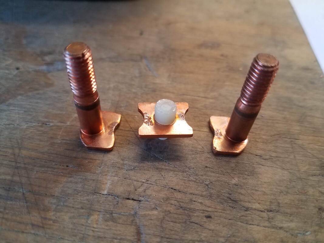
Regulator Diode Testing Connect your diode tester to a Stator wire and check for diode current flow through the positive and then the negative terminals of the DC output voltage connector. One of the DC terminals should show current flow...only one. Then reverse your diode tester connections and check the same points. Now the OTHER DC terminal should show diode current flow while the one that flowed before should indicate blocked flow.
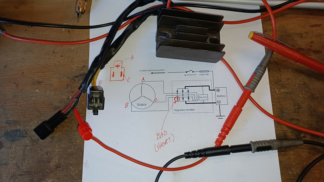 Results from an actual Regulator Assembly Test (which showed one shorted diode) In the example shown here, current was found to be flowing from terminal A on the Stator to the positive (+) DC terminal of the Regulator (which it should) AND to the negative (-) DC terminal of the Regulator (which it should not). That measurement proved that this was a bad regulator. It must be noted that testing the diodes in this manner CANNOT conclusively prove a Regulator is good. Such a test can only prove that a Rectifier part of the Regulator is bad. The diodes could all be just fine and the regulating circuits themselves could be bad, resulting in bad system voltage on the bike. However, in this case, testing revealed at least one bad diode inside the Regulator assembly, so it is a gonner. Additional Tests
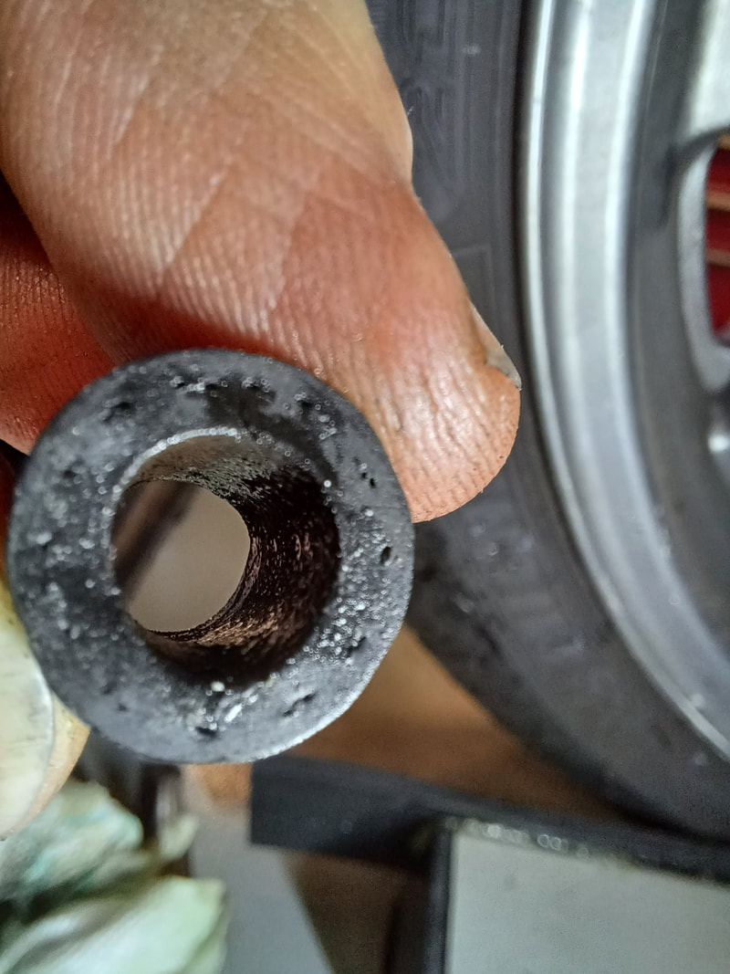
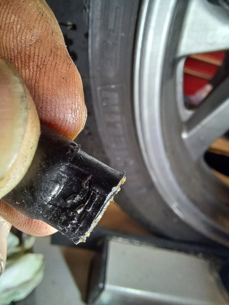
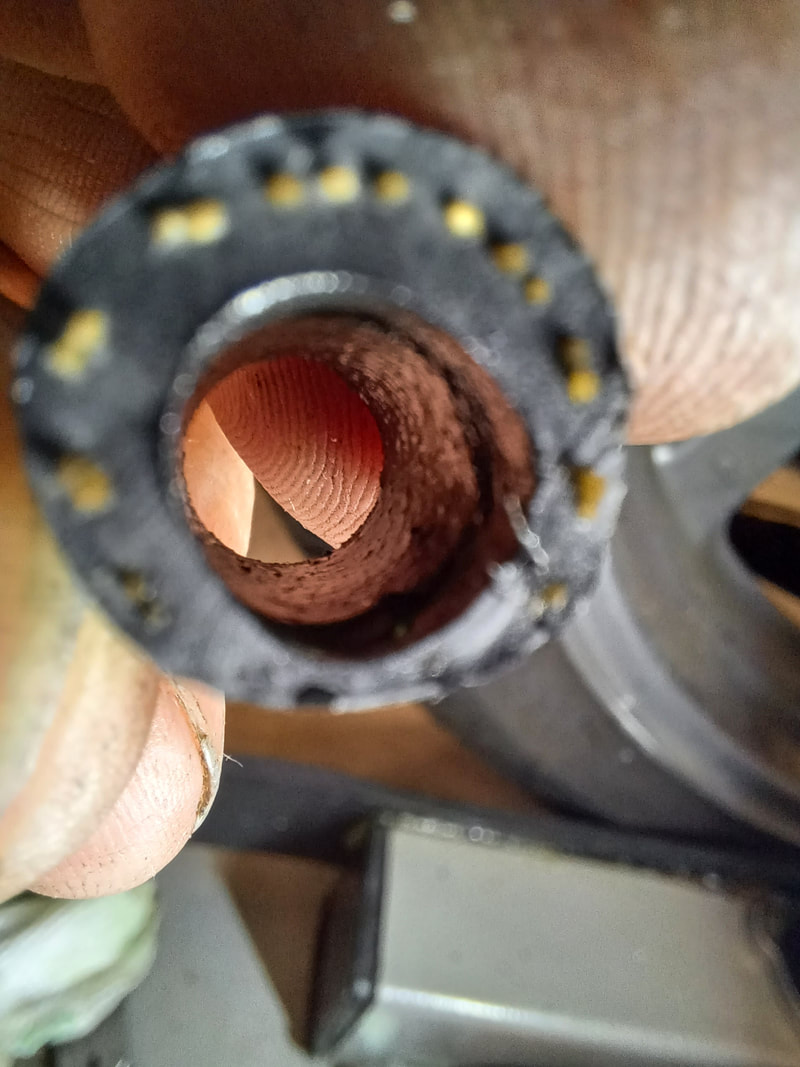
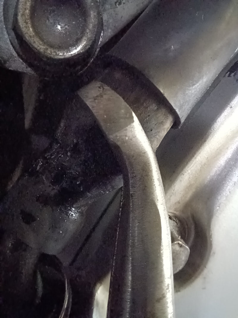
Once you have determined the major components of the charging system are functioning with the bike turned off, there are other tests you can do with the bike is running. With the engine running AND the Stator unplugged from the regulator, check AC voltage between each of the three Stator output terminals (Three measurements...on the drawing above would be point A to B, A to C, and B to C). The voltage seen at any given engine RPM should be about the same for each measurement (because the coils and magnets are the same for each phase). You may see nearly 100V AC on these terminals, so be careful. Anything much past 24 volts can be noticeable and 48V and up can hurt...and can certainly be deadly. Watch yourself. This test is particularly useful if the Stator is wounded and only shows a short at higher voltages or only shows an open when it is being vibrated by the motor. The key for each of these measurements is that under the same conditions, they should match each other pretty closely (say +/- 10%). Needless to say, if you see bad results in these tests, you have a bad Stator and need a new one. Repeat the measurement of the AC terminals with the Regulator plugged in. Again, each phase should be the same as another...although probably not the same voltages seen when the Stator was unplugged. Seeing generally lower voltages would be normal because the Stator is doing real work if it is plugged into the Regulator. But be on the lookout for seriously low output voltage on any phase of the Stator. A bad Regulator may collapse the Stator AC output on any or all phases. One low or high phase measurement when the Regulator is plugged in, despite seeing uniform AC voltages on each phase of the Stator when the Regulator us disconnected, suggests a bad Regulator. With the Stator and the Regulator connected normally, check the DC output voltage of the Regulator with the Regulator connected bike. For reference, check battery voltage first and keep that number in mind. Then start the bike and check battery voltage while it is running. Whatever voltage you see at idle should increase somewhat as you increase engine RPM but should stop climbing once it gets into the 14.5V to 15V range. If, when you are at 1500 RPM (high idle), it is not at least equal to the battery voltage you measured when the engine was not running at all, something is wrong (perhaps a bad Regulator, but possibly a bad Battery). If DC voltage keeps climbing past 15V when you increase RPM, STOP THE TEST before you blow bulbs or worse on your bike. And get a new Regulator. Disconnect the DC output of the Regulator from the bike and check Regulator output voltage while the bike is running, again slowly increasing RPM, checking to see how much output voltage increases as engine speed increases. If it is too low to charge your battery (say, less than 12.6V DC) or too high (say over 15V DC), you have a Regulator problem. Just finished a water pump job. Everything is clean and tight. Got the radiator full, topped up the overflow tank, fired her up, watched for coolant flow when the thermostat opened, put the radiator cap on nice and snug, and… 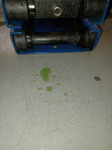 DANG…there is a leak…one stinking, little, slow drip…on the smallest hose in the system. WTF. 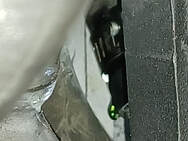 There it is. Right under the hose clamp. How is that possible? Well…here’s how. The end of the hose is nice and round and thick…like the rest of the hose. But, uh oh, look at where the clamp has been on the hose. Yep…there’s the hole; right under the lead screw housing. Cutting off the hose end affords an even more telling look. The hose was completely distorted. The flat bottom of the worm drive housing squashed the life out of that poor little hose…squashed a hole right through it.
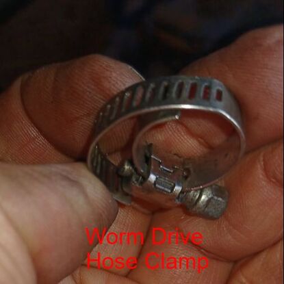
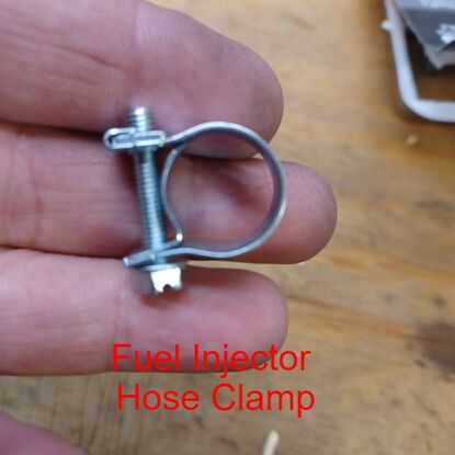
Oh yea…the smallest hose in the system needed a better small hose clamp; one that does not have a flat spot in the clamping surface like the one on this worm drive hose clamp that had been used on this hose. Here’s one option…a fuel injection hose clamp.
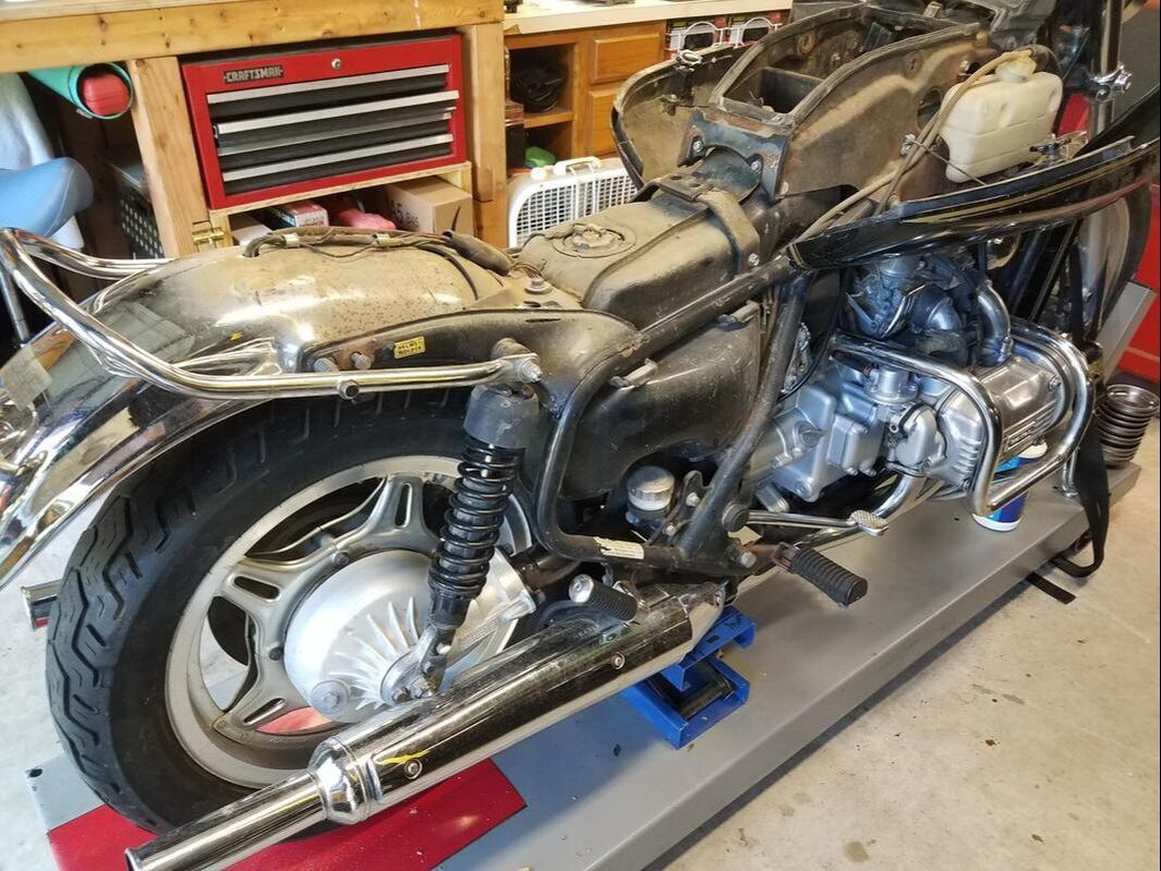
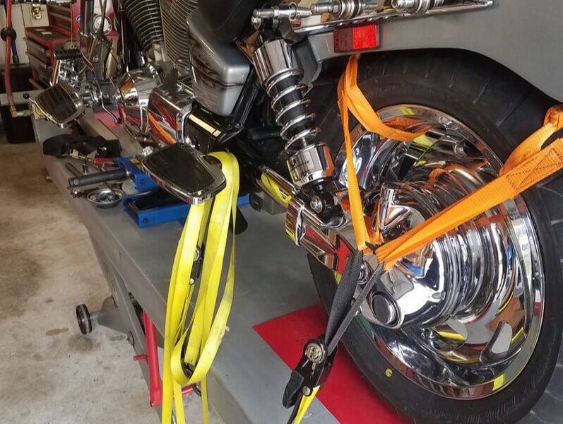
Note how the clamp is designed to deliver clamping force uniformly around a small hose. Make no mistake, even these clamps can be applied in a way that causes a pinch right there under the screw. (Don’t ask me how I know that.) The trick is to get the metal clamp to slide smoothly around the hose as it is being tightened. How? There is a magic rubber dressing that can be used to gigantic advantage every place rubber comes into contact with metal and needs to move, rather than stick. It is awesome for sliding stubborn hoses onto or off of water pump or radiator fittings, it is the bomb for demounting and mounting tires (that’s right…dump the soapy water…this stuff will change your life), it is the coolest for slipping wires through jackets. What is this magic stuff? It is already on your work bench; plain old WD-40. That’s right. It works miracles on rubber when you need to get it to slide past some metal…and then it evaporates away, leaving newly mounted tires or hoses or hose clamps, clean, dry, and ready to go to work. So, yea, this is a twofer. First, you learned NOT to use ordinary worm drive hose clamps on any hose where the flat spot in the worm drive mechanism represents a significant portion of the circumferences of the hose to be clamped (i.e. a too small hose). If you do, you risk putting a flat spot in your hose…and causing a leak. Second, you learned that, when it comes to fitting rubber parts, WD-40 is your best friend. 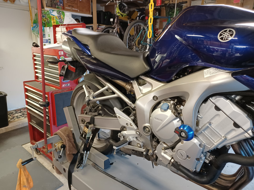 Backwards? Well, yes. Normally it is the front wheel that goes into the wheel vice at the front of the lift. Why not this one? Because this bike needs a new front tire. The front end needs to come up off the ground, not the back tire, to service this bike...but that is not the whole answer. A bike lift (a.k.a. a lift table) allows a mechanic to work on a bike without crawling around on the floor. If you work on a lot of bikes or are not 20-something anymore, a bike lift is a godsend. But sometimes, the bike needs to be lifted up from the lift table...the wheels need to be in the air, perhaps, as in this case, to remove a wheel and change a tire. What is a mechanic to do? The easy traditional answer is a small scissor jack, like the one shown in these photos:
The scissor jack is the little blue gizmo sitting between these two bikes and the lift table surface. Capable of lifting 1000 lbs., it is very handy item to have. But there is a catch. The bike you want to lift has got to have some solid structure on the bottom for the jack to contact that can bear the weight of the bike as the jack lifts it off one or both of the wheels. In the first photo, the rear wheel of an old Goldwing is being lifted while the front wheel is clamped in the wheel vice. It should be noted that this allows the bike to rotate (however slightly) about the front axle, without stressing any of the frame elements. In the second photo, the front wheel of a VTX is being lifted, while the rear wheel is strapped down to the table with the two orange "Y" straps shown and a matching pair out of view on the other side of the wheel. This allows the bike to rotate around the rear axle, without stressing any frame elements, yet, as in the first photo, the bike is being securely held upright, even as a wheel lifts off the table surface. But I digress. The central story here is the handy little blue scissor jack...and why it couldn't be used this time. 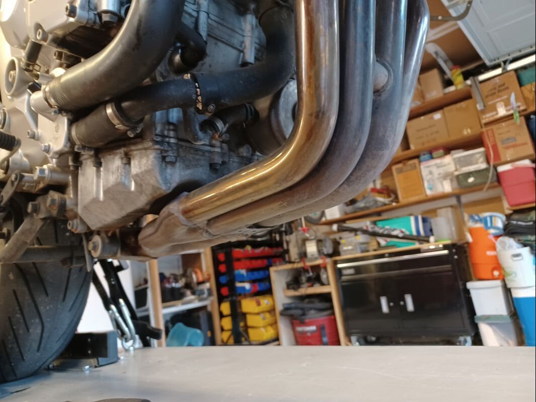 Here's the bottom side of the FZ6. No solid structure down there; nothing but exhaust pipes. Lots of bikes are like this...particularly sport bikes. Do not be the poor fool who lifts his bike by putting a jack under the pipes. You will not like the results. Sure, if we wanted to lift the rear wheel, we might get a jack to contact something near the back, like the pivots for the center stand...but to lift the front, the lift point needs to be in front of the bike's center of gravity...and that looks like a problem. Fortunately, somebody has solved that problem. We can use a "Head Stand". 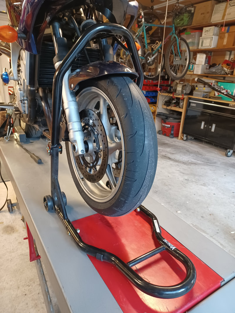 Even if you hated High School Geometry, you are going to love a Head Stand. A Head Stand us a wonder of geometry and the power of leverage. The stand has hinged uprights, a lifting pin at one end, the lever end (the hoop handle shown), and wheels that allow the whole affair to pivot as the hoop handle is pressed downwards. As the handle goes down, the wheels roll forward and the pin is lifted upwards as the uprights go from folded, to straight and locked (as shown here). It takes a little effort, but not so much that even a skinny mechanic would find difficult. 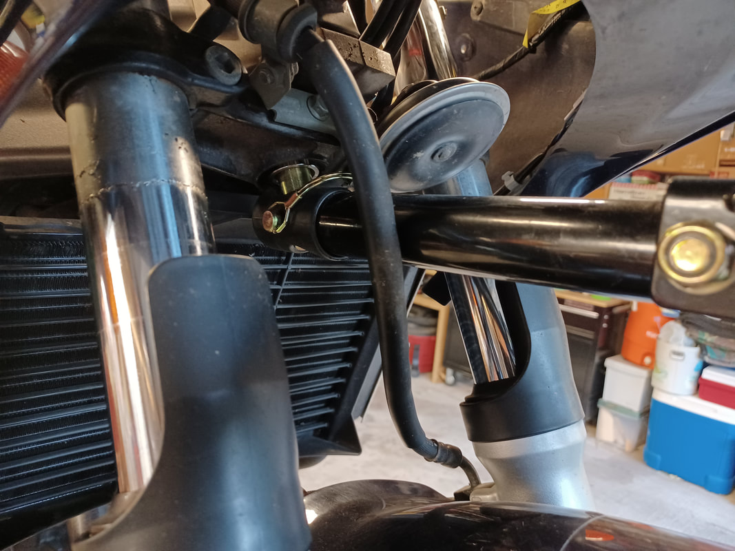 The pin, as shown here, goes into the hole found at the bottom of the steering head on almost every bike. Those holes come in a variety of sizes, so if you plan to work on lots of different bikes, you get a bunch of different pins, not a bunch of different stands. The steering head is always located above the bike's center of gravity, so a bike will always hang securely from the lift pin, without any danger of the bike flipping over after it is lifted.
The downsides of using a Head Stand are:
However, since the front wheel will still pivot left to right, obstruction caused by the stand legs can mostly be avoided. Not having the ideal lift height is more problematic, which is to say, can usually be addressed with a little more effort and innovation (e.g. you may need to do a little more disassembly than would have otherwise been required to get additional clearance, or you may need to slip something under the lifted wheel to reduce excessive clearance). One word of caution: Head Stands should not be used alone...that is without some sort of REAR stand or clamp. You might get away with using only the front stand, but you might not, and having a bike topple over just isn't fun. Use a rear stand or a wheel vice or some other sort of rear wheel tie-down to make sure the bike stays upright while it is being lifted. Yes, I know I said earlier that the bike's center of gravity is below the steering head...but it may not be far below, and if that is the case, removing the front wheel or the bike being jostled side to side might result in a tumble. So...play it safe. Secure the rear wheel before you lift the front. Bottom line, Head Stands are a very useful and inexpensive tool...and one of very few reasonable ways to lift the front end of some bikes. If you need one, get one. You won't regret it. 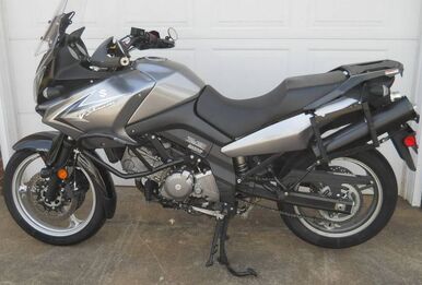 A very pretty 2009 Suzuki V Strom 650 came into the shop last week. She looked showroom fresh, with less than 2k miles on her. Needless to say, she had been parked for years...and sadly, with a half full tank of gas...which, predictably, turned into a tank full of rust.
The owner had already cleaned the tank and replaced some or all of the fuel pump assembly, which lives inside the tank itself, but despite these ministrations, she would bog down under load. She idled like a champ, but just wouldn't pull when the rider cranked on the throttle. Very frustrating for the owner. There are a number of esoteric possible causes for that behavior, but the most obvious thing to check is fuel pressure, which is a proxy for looking at fuel flow. This is a fuel injected bike, so fuel pressure is supposed to be pretty high, around 60 PSI. Fuel injectors just won't work right if the pressure gets too low. And if the fuel pump assembly cannot keep up with the fuel demand from the engine (as the engine control computer tries to get it to make more power), then the fuel pressure in the fuel supply line is going to drop. Because spraying 60 PSI gas around your shop is a bad idea, selecting the right fuel pressure test rig is important. Fortunately, bike manufacturers have largely selected standardized fuel line fittings when they design their bikes. In this case one of the mid-size quick disconnect fittings was just the ticket and that allowed disconnecting the fuel line from the tank, plugging in the tester T-connector, reconnecting the fuel line to the Tee and then hooking up the pressure gauge to the open end of the Tee. The results can be seen at the links below... Start and Blip Throttle and Advance to Higher RPM What you see here is a significant drop in fuel pressure as engine RPM is increased...despite the fact that the bike is just sitting in the shop in neutral, not even spinning the back tire. So even with zero load on the engine, the fuel pressure drops...a lot. You might even notice in the second video that you can hear the RPM begin to drop (despite increasing throttle) when fuel pressure gets near 20 PSI. It is significant that the pressure drop is smooth. Pressure rolls off steadily as RPM increases. It does not, for example, spike low intermittently and then pop back, which might suggest an intermittent electrical connection to the (electric) fuel pump. Nope, this sure looks like plain old low flow. The fuel pump assembly just cannot keep up. Now why say "fuel pump assembly" and not "fuel pump"? Because inside the tank there is not only a fuel screen / filter, there is also a pressure regulator, as well as the pump itself. Poor flow could be caused by problems with any one of them, not to mention the possibility that the fuel pump assembly components themselves may have been misassembled and are leaking fuel from the pressurized lines inside the tank into the low pressure area inside the tank itself. That would not produce a fuel leak that is visible outside the tank, but it could cause a pressure drop in the fuel line when fuel demand increases. So, how did this all turn out? We don't know yet. Now that he has a solid answer on the fuel pressure question, he and his bike are back home awaiting the arrival of a new Suzuki OEM Fuel Pump assembly, which he will install after taking another good look inside that tank...to see if another cleanup is in order before installing the new pump. Stay tuned! What does every mechanic want most? New wrench set? A better set of screwdrivers? Nope. In the middle of just about every job, at some point we say "Damn, I need one more hand!" 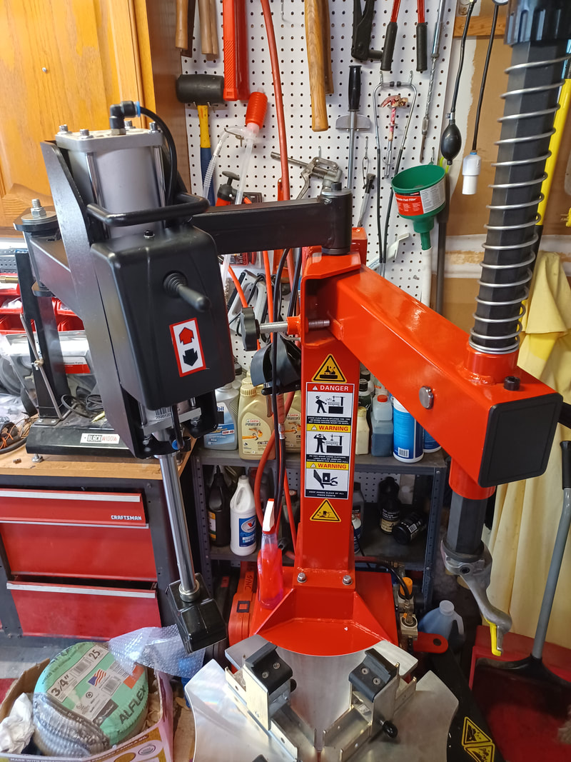 Well, when it comes to changing tires, it couldn't happen more often. Fortunately, some bright guy came up with a way to add and extra "hand" and a very strong arm, to a tire changer.
The need is pretty simple. To demount or mount a tire, the sidewall needs to be pushed towards the center of the wheel. Some tires make that VERY difficult, particularly, low profile, high performance tires...the sort you might find on large, powerful bikes. With the advent of "helper arms" on tire changers, jobs that are very difficult with conventional tools become far easier...if not downright easy. The helper arm, the black mechanism shown above, swings an air ram that is attached to a plastic foot, over a wheel and tire that has been clamped to the turntable. With the press of an air valve, the ram presses the foot down onto the sidewall as far as necessary to put the bead into the "drop zone" (the smaller diameter inner section of the wheel) which now gives enough clearance for the tire to be shifted sideways on the wheel, allowing the bead to be lifted over (demount) or pressed past (mount) the opposite side of the wheel. The arm is double jointed and the foot pivots, allowing the air ram to maintain pressure on the tire, even as the wheel is rotated on the turntable. Pretty nifty. CLICK HERE to see it in action! 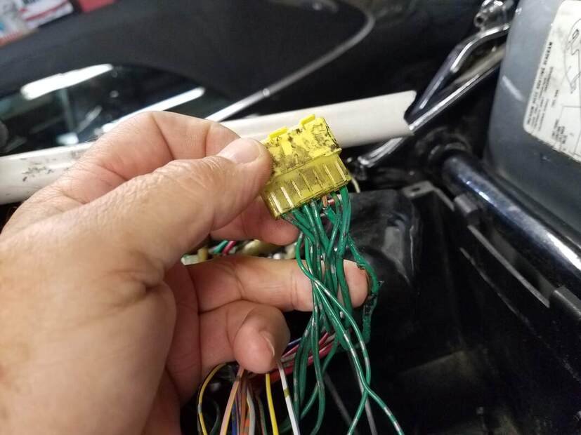 See that burned wire? When this 2002 Honda VTX 1800C heavy cruiser came into the shop, she had been parked for 5 years with an electrical bug. Over the months preceding her last ride, she had run worse and worse until finally an attempted restart resulted in smoke curling up from under the seat and fuel tank. The owner wisely gave up trying to start the engine so, thankfully, a fireball was avoided. The owner had some wrenching experience, so he pulled the seat and tank and found burned wires but no blown fuses. Nobody seemed to have any clues about what to do, so the bike just sat. When the VTX came in, other than being partially disassembled, she was pretty as a picture...but missing her battery and had a third of a tank of rusty gas. Some of the smoked wires were visible and the story was that she had run very badly at low RPM before she finally died, and that part of the difficulty before the bad running developed, was that attempted starts often failed because the starter motor often wouldn't turn. Some mechanical pundits had suggested a bad battery, others suggested a bad starter, others suggested a bad starter relay, all of which had been replaced on various occasions to no avail. Very interesting. Step one was a deep dive into the bike schematic to see how a GROUND wire in the harness could burn up without blowing any fuses. Interestingly, the bike did have a Honda Service Bulletin for an electrical issue... The VTX-1800C, for a time, rolled out of the factory (a USA factory) with the far end of the main ground wire from the battery connected to the wrong place on the frame of the bike. But that fix, putting the ground lug where it belonged, had been long since done. Something else was amiss. Close reading of the schematics and tracing out where all the ground wires went didn't offer much help. Everything in the schematic looked pretty normal. The fun started when the bike wiring itself was compared to the schematic. Uh Oh... 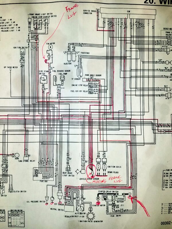 The bike itself was missing a ground lug connection...THE ground lug connection...the main ground junction in the wiring harness where all the smaller ground wires from all over the bike come to a single ground lug that gets solidly bolted to the frame. The result was that ground current from every device on the bike that was not itself grounded directly to the frame (such as the Fuel Injection System and the Starter Relay) was being routed through a very small wire that ran about two feet long from the harness ground junction under the seat (shown in the photo at the top of the page), under the gas tank, to a small secondary grounding lug adjacent to the radiator at the front of the bike. Yep, you guessed it...the very wire that had gotten so hot it melted and/or burned away its insulation. Other high current items like the spark plugs, the starter motor and the radiator fan motor were all grounded directly the the frame itself...which was connected back to the battery with the big fat battery ground wire via the now repaired battery cable main frame lug. But there was still lots of stuff sending current back to the battery by way of this poor little, now smoked, green wire. How could this happen? The missing harness ground lug was so bizarre, customer modification of the bike was the most likely explanation...but a call to the local Honda dealer techs confirmed that the connector with the burned wire but no lug, was indeed a stock Honda connector. There is only one explanation, this was a birth defect. The Product Engineer(s) responsible for the manufacturing of the bike at the factory had screwed up TWICE, first by allowing the battery wire frame lug connection error to enter production (resulting in a Service Bulletin), but also by allowing the elimination of the main harness frame lug. Clearly, the bike design team knew the lug was needed to handle return currents from all over the harness. It was right there in the schematic...but not on the bike. That is on the Product Engineering team. That ground lug should not have been eliminated. In fact, it is likely that the missing lug has actually been the primary problem that has plagued VTX 1800s all along...and that the Service Bulletin cured an inconsequential problem but missed the real issue. So why don't all VTX 1800s burn up the little wire that runs from the ground junction to the secondary ground lug? Obviously, the little ground wire was good enough to work kind of ok, at least for a while. Lots of bikes rolled out that door that way without immediately catching fire. One of the things that happens with overloaded wires, even if they are not overloaded badly enough to burn immediately, is that the heat in them slowly bakes the insulation around the wire, causing it to become dry and brittle, eventually causing the insulation to flake off and expose the copper conductor inside. If it is a power wire and that bare copper touches a grounded frame member, sparks fly and fuses blow. However in this case, if a ground wire touches a grounded frame member...nothing happens. It's a ground wire. That is where it is supposed to be connected. So in this case, that is not too big a deal. But because the wire was buried inside the big wire bundle that runs from the front of the bike back to the battery and the computer, making contact with an adjacent power wire in the bundle was a real possibility. Testing revealed that, fortunately that had not happened. The next problem is that the wire's connection points can overheat and carbonize, slowly offering more and more resistance to current flow. At first, that might seem ok too...more resistance results in less current flow and less heat. Sounds perfect. Well, not quite. Passing current through a resistance results in a voltage drop across that resistance. That is how they make electric heaters...the ones that get red hot and keep your feet toasty in the winter. Just how hot it gets is a function of power (watts) and the volume within which that power is being dissipated. If the volume of the conductor where that current is flowing is small, then all the power, all the watts, are being concentrated in that small space...and the temperature in that spot can become VERY high. (That is exactly how an Arc Welder works.) As a result, what may start as a small problem can get worse and worse (a little heat degrades the connection a little, but as time goes by, resistance in the connection gets higher and higher until it finally burns up). But on the way toward that fiery end, all the other items in the circuit served by that connection are being starved for voltage. If it is a 12 volt circuit and 3 volts are being dissipated across the resistive connection, then only 9 volts remain to serve the load device...say the Engine Control Computer, for example. Now we have a plausible explanation for what happened. The overtaxed ground wire slowly got worse and worse, stealing voltage from the engine computer...which controls both the fuel injectors and spark plug pulses. Is it any wonder this bike was running worse and worse until it finally gave up the ghost? And guess which electrical component on the bike that uses the harness ground junction, is the one that consumes the most current when it is operating? That's right, the starter relay; the relay that gets activated when you punch the start button. It was during attempted starts that the overloaded ground wire finally sent up smoke signals. The solution? Rewire the main ground junction to a new frame lug to conform with the schematic...and replace the fried wire that ran from the harness ground junction to the secondary frame lug at the front of the bike. And just to be double-dog sure this NEVER happens again, do a complete overkill on the job and use 8 gauge stranded copper wire to do it. So...with the ground wire and ground lugs fixed, everything should be perfect, right? Yea...not so much. Now with the wiring fixed and a brand new battery installed, attempted starts are a complete crapshoot. Sometimes they work and sometimes the bike does absolutely nothing when the starter button is pressed. Jeez now what? A trouble light connected to the relay coil quickly proved that the relay was getting juice every time the start button was pushed, which was no surprise since you could hear it click every time the starter button was pressed. The problem was the starter relay, the one the customer reported was fairly new (as a result of an earlier failed attempt to cure the hard start problem). Fortunately, it is a quick* fix. Yank out the old one and bolt in the new one, reconnect the battery and off she goes. (* Quick, not cheap. A replacement OEM relay was ~$40. Aftermarket relays that looked exactly the same could be had for less than $10...but buyer review reported very high failure rates...so Honda got the order.) But a bad relay is a bit of a mystery. Generally they are either good or bad. This one showed wildly different contact resistance measurements every time it is tested. So (naturally!), an autopsy was in order. After ripping it apart and looking at all the parts, nothing seemed to be wrong with it . Sure, the internal contacts looked a little pitted...but can that be so bad. Well, it turns out, YES!
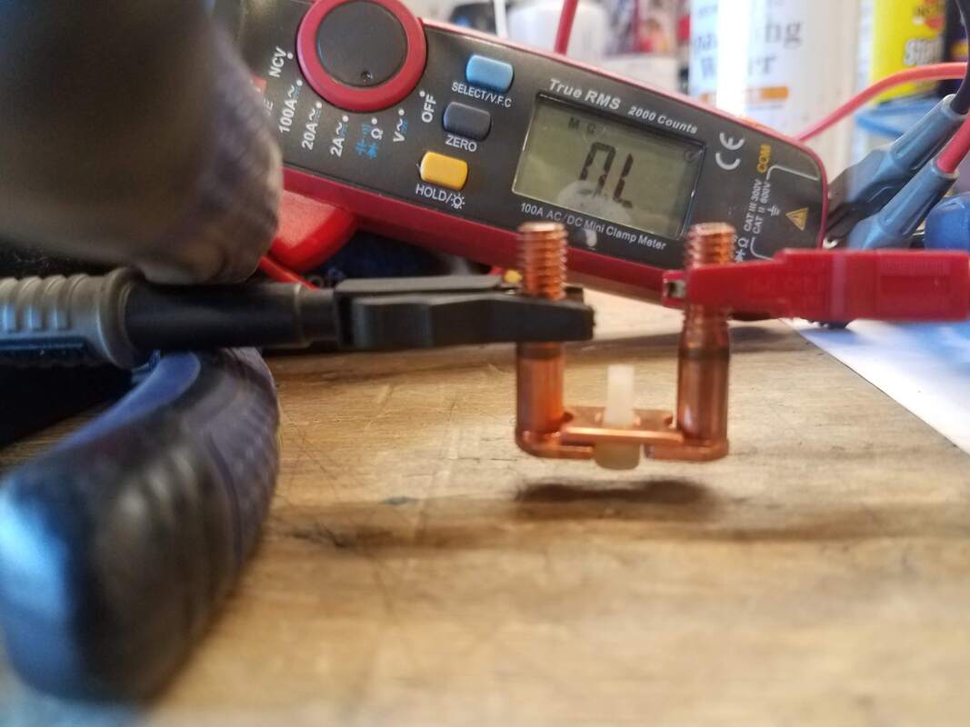
Connecting the main terminals to an ohm meter and then placing the contactor across the gap (just as it would be when the relay has activated), results in the meter reading "0L" or Over-Range, meaning Infinite Resistance...no circuit, no current flow. no go. These are all solid copper pieces. How can this be? Clearly the carbonizing and pitting shown above on the left is enough to kill current flow in the picture above on the right. Now we have the cause of the no starter reaction when the starter button is pressed...and sure enough, with the new starter relay installed the bike fires right up...
...most of the time. Well, dang. Now what? Sometimes when the starter button is pressed, the starter motor just cannot make the engine spin. And sometimes, it moves it just a bit...and then stalls, like it suddenly got stuck in glue. What's up with that?! Now we finally know why this VTX burned up its overtaxed harness ground wire. It has a failing (or failed) compression relief valve in the engine. Engines with big cylinders (and this 1800cc Twin has some of the biggest they make) have a compression relief system that reduces the air pressure inside the cylinder when the engine is spinning a very low RPM, such as when it is trying to start. Why? Because it is very difficult to get the engine to turn in the compression stroke...when the intake air and fuel vapor charge that the spark plug is about to ignite is being compressed toward the spark plug. If the bike has a kickstarter, a light weight rider might not be able to kick start a big bike without a compression relief system...and if it has an electric starter motor, a successful start without a compression relief system might require both a larger starter motor and a larger battery, which would take up more space, add weight and expense to the bike. But a compression relief system, like any system, can fail and it can fail in at least two different ways: It can fail active and it can fail inactive. In other words, it can fail to relieve pressure when it should or it can get stuck and always relieve pressure, even when it should not. In this case, it looks like the compression relief cam (a spring loaded movable cam surface built into the valve camshaft mounted on top of the cylinder head on each cylinder) is failing to deploy when the engine stops, such that when a start is attempted, IF the engine has stopped right at the start of one cylinder's compression stroke (Reminder: The four strokes of a 4 stroke engine cycle are: Power Stroke, Exhaust Stroke, Intake Stroke, Compression Stroke), then even a perfectly healthy starter motor might not be able to spin the motor. In this engine, the movable cam cracks the exhaust valve open on the Compression Stroke, wasting a little fuel/air mix, but allowing the engine to spin more easily...and therefore faster, to start more easily. Once the engine fires and quickly spins up to idle speed (about 1000 RPM) the cam retracts and full compression is restored, allowing the engine to run at full power. If the cam fails to retract, the fuel waste and reduced compression both conspire to reduce engine power output. So what does this have to do with an electrical failure? Here it is. When the engine is asked to start in a high compression state, the electric starter motor stalls. The starter motor consumes a tremendous amount of current in this condition...over 100 amps. The rider may continue to keep the start button mashed in, or may release it, only to hit it again. The contacts in starter relays are pretty tough, but they are not designed to handle the kind of current flow for more than a fraction of a second. (That current flow drops considerably when the starter motor starts to spin.) Nor are they designed to handle lots of restart attempts in a short period of time. Each start attempt heats the starter relay contacts...and enough start attempts in a short period of time could start to burn the contact surfaces. So the pitted / failed starter relay contacts are not a big surprise at this point. But what about the melted ground wire? As mentioned earlier, the starter motor current does not pass through the wiring harness at all. (See the schematic above.) It leaves the battery, goes through the main lugs of the starter relay, flows through the starter windings, into the bike engine case and frame, and from there, through the main battery wire ground lug, through the battery ground wire and back to the battery. It never goes through the wiring harness at all...BUT...the current that activates the starter relay, that flows through the starter relay windings, that current does go through the harness ground junction...and the starter relay has a big honking winding, that consumes multiple amps of current when it is activated. Bingo. That is where the intermittent high current flow, that eventually fried the overloaded ground wire, was coming from. So...here's the sequence. The spring-loaded, centrifugally released, compression relief cam on the exhaust valve overhead cam lobe (at least occasionally) fails to deploy when the engine stops, making the next start much more difficult. Repeated attempts to start the engine against full compression causes lots of current draw, arcing and pitting of the starter relay contacts, making starts even more difficult...and encouraging the rider to keep the start button engaged for excessively long periods and/or in excessively rapid succession. The high current draw of the active starter relay coil adds to the already excessive current flow through the soon-to-be-fried secondary ground wire as it heads for the secondary harness frame ground lug, because the primary harness frame ground lug is missing...and the wire starts to smoke, creating a general sense of alarm in those around to witness the smoke rising from under the fuel tank. So...what's next? If the fix were free, then determining which of the two camshafts (one on top of each cylinder) has the bad compression relief cam would be next...and it could be fixed or more likely, replaced. However, for the owner, who is not made of money, there is an alternative, at least for now. Live with it. Because the engine does not always stop at exactly the same spot in its cycle, the problematic piston is not always the one that is up to bat. And perhaps the defective mechanism does not get stuck all the time. The fact is that the bike starts just fine somewhere between half and three-quarters of the time. So it falls to the rider to address the problem properly when the problem occurs.
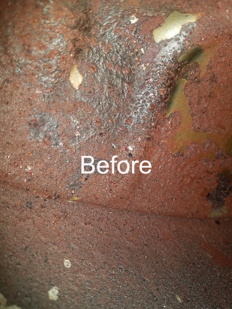
Assuming the failing compression relief system does not get any worse, the owner should be able to operate the bike without too much trouble, saving the near $1000 repair bill that would likely be waiting for him at the end of a camshaft replacement project. Not bad; huh? Now, what about that rusty gas? 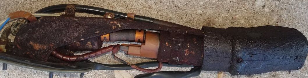 Much better... This is the result of about one gallon of gas left in a three gallon tank for five years. The nasty object above is the in-tank fuel pump and integrated fuel filters. That is pretty easy to fix. All you need is $500 and the time to remove it, rebuild or replace it, and reinstall a few bolts. Not cheap, but pretty easy. (Sure, you need to drain and remove the gas tank, which may require a pump and lots of disassembly time...and then you need to put it all back together correctly, but that isn't rocket science either.) The inside of the tank itself is a bigger problem.
The rehabilitation of rusty fuel tanks seems to be a religious matter. Doctrine ranges from "Don't...just replace it", to "Clean it and coat the inside with (insert the name of some sort of paint-like product here) ." And recommended methods for cleaning are all over the map too, ranging from "Rinse out the chunks and call it done." to "Fill it with (wood screws, abrasive, BB's, etc.) and (shake it, tumble it, vibrate it, etc.) . I have tried some alternatives and today I generally take a middle of the road approach. I will say, if I had a big tumbler system or high powered ultrasonic wand that I could insert, I might do differently, but I don't. So I keep it simple.
I do not paint / epoxy tank interiors. I believe it is risky (the paints can degrade / flake off) and that fuel filters are really pretty good. Sure, keep a weather eye on your fuel filter(s) after you start riding again. If they start filling with rust then further intervention may be needed. But if you care for your tank with two final steps, that is not likely to become necessary. Step 9 - Fill your tank all the way on your way home from each ride. The water in the tank does not (mainly) precipitate out of the gas. It mostly enters your tank in the form of humid air. Once inside, the water condenses out of the trapped air in the tank and falls to the bottom of the pool, where it does its dirty work. If there is no air space at the top of your tank, there is no water vapor to condense inside, and your rust problems are considerably reduced. Naturally there are other alternatives. You can drain the tank absolutely dry. That works too. Step 10 - Ride often. (Or at least run the engine for a half hour each week...and then top up the tank with new, not stored, gas.) But here's a word of caution regarding that full gas tank. Modern Ethanol-mix fuel harbors bacteria that eat ethanol and piss Acetic Acid...which will eat everything metalic in your fuel system, especially aluminum parts. Yes, I know I just recommended filling a rusted tank up with 30% Acetic Acid, but I also said get it all out when you are done. The bacteria in your tank are kinda slow growers, but if a tank has been sitting for a month or so, even a completely full tank, the bacteria bloom is underway and will accelerate exponentially over time until the bugs die in their own piss. If you have ever seen and/or smelled green fuel in a tank, you have seen the aftermath of a bloom for yourself. If you are not going to keep fuel rotating through your tank (burning up the blooming bacteria and re-filling with fresh gas) then at least use a fuel preservative product like Stabil, to keep the buggers at bay for a few months. If it is going to be longer than that, drain that tank...completely dry. (Full disclosure: water does come into the tank mixed in solution with the ethanol in the fuel. Water does not mix with gasoline, but it does mix beautifully with alcohol, as your bartender can readily confirm. And any batch of ethanol-gas you get may have water trapped in the ethanol. If you get a tank with high water content, the next tankfull is likely to dilute the concentration of water in the tank. Just another reason to keep using the gas in the tank regularly.) So...either drain that tank dry or fill it full and burn some off every week. Don't give rust a chance. Like Neil says, better to burn up than it is to rust.  One of Many Brands One of Many Brands Internal combustion engines need three things to run. Fuel, Fire and Compression. If the correct amount of fuel (and air) is in the cylinder, and the mix is properly compressed (to somewhere near 1/9th of it's uncompressed volume), and it gets a spark, the mix will explode. Physics. It cannot do otherwise.
Granted, lots of things need to happen properly in an engine for all that to come together and happen at the right time in the piston cycle, but that remains the core principle of internal combustion engines. To troubleshoot an engine that is not running, or not running properly, those are the three main issues to consider. COMPRESSION Lots of things can cause a loss of compression, but they all come down to the cylinder having a leak. Mechanical wear, blown gaskets, defective seals, dirty / leaky valves or bad valve timing can all cause a loss of compression. Fortunately, serious compression loss is fairly rare...and that is good, because it is always the most expensive problem to solve. Engines are built, first and foremost, to continue to hold compression through their service life. The good news is that if you have verified fuel and fire, checking compression is among the easiest test to do on an engine. Still, it is rarely a sensible place to start your troubleshooting. Failures in the fuel supply and ignition systems are far more common. FIRE Outside of flat running out of gas, ignition failure is by far the most common cause of an engine failing to run. And that is great, because it is the easiest problem to check directly and is often the cheapest problem to fix. The easiest ignition check is to unplug a spark plug wire, remove the spare plug, reconnect the plug wire, ground threads of that plug to the block, and crank the engine. If you can see a nice blue-white (or even reddish) spark you can PROBABLY say ignition is ok and move on. I say "probably" because if you do see a spark, you still do not know if the spark happening at the right time. If you don't see one, you do not yet know why. Maybe the plug is bad, or maybe other ignition components are bad and you still need to track that down (or maybe the kill switch is turned on!). But at least you know the next path to follow. But, there is actually something that is even easier to check, if only indirectly. And since we are trying to zero in on the main problem area quickly, easy counts for a lot. And the easy test involves the third leg of the stool...and is often a great place to start your troubleshooting. FUEL So, we have already assumed you are not out of gas...but on a small engine, you better make sure the fuel valve (often called a "petcock") is open and fuel is actually flowing. Next up on smaller machines, including most motorcycles, is the carburetor, which regulates the amount of fuel that is supplied to the engine under various throttle and load conditions. Larger, more sophisticated, less polluting, engines get their fuel via a fuel injection system. Let's start with carbs. Carbs have tiny passages in them, through which tiny streams of fuel flow, that ultimately get mixed with the air coming into the engine. Just a little schmutz in any of those passages can put a carb out of commission. A failed fuel pump or clogged fuel filter can also stop the music (in fuel injected motors too). If your machine has been sitting for a few months with fuel in it, there is a very good chance your carb is plugged up and needs to be cleaned. But let's not jump to conclusions. While you can look at spark plug and get a pretty good idea of whether or not it is sparking, you cannot just look into a carb and see whether or not it is working properly. Fuel injection systems in gasoline engines are almost always computer controlled, and with proper diagnostic tools, can often tell you if and why they are sick. But for a carbureted engine that has no blinky lights, it is not so easy. What to do? Well, obviously, you cheat. (And the cheat actually works on fuel injected engines too.) One of the products you will find on the shelf at every auto parts store is a can of "starting fluid" or "starting spray". The can will contain a cocktail of flammable chemicals, usually including ether, which vaporizes easily and happens to burn like crazy. A spray can of starting fluid is a great diagnostic tool. Remove the air cleaner so you have a clear shot at the intake, give it a one second blast of ether, and immediately crank the engine. If it fires and runs for a few beats (perhaps for a few seconds), you now know that you have reasonably good ignition, firing at (at least approximately) the right time. You know you have at least marginal compression. And you know that you just supplied the missing element...fuel, more specifically, vaporized fuel. (Engines do not run on liquid fuel. They run on vaporized fuel.) Now you have a pretty good idea where to look...the fuel delivery system. Ignition may not be perfect, but it was good enough to fire the ether. Compression may not be perfect, but it was good enough to explode the ether. So right now the fuel delivery system is the prime suspect. Conversely, if the engine did not fire with ether, you PROBABLY have an ignition problem and should at least do the easy ignition test (pull a spark plug and check for good spark). If you see good spark AND the motor will not fire on ether...well, now you are in for an education. It is time to dig deeper.  So...you aren't supposed to talk about religion and politics in gentele company, right? Well, I am going to put on my big steel-toed boots and stomp right into the middle of a hot religion topic in motorcycling...using car tires on motorcycles.
"What kind of lunatic puts a car tire on a motorcycle?", you might ask. I cannot say with absolute certainty, but the evidence suggests to me that they are, at their core, shortsighted cheapskates; the sort who try to seal up a cavity in their tooth with superglue to avoid paying a dentist, only to reap an abscess and need dental surgery later. Why would someone even consider this insane idea? Well, motorcycle tires are not cheap, particularly not good motorcycle tires. And the labor charges to install them are often almost as much as the tires themselves. So it can cost almost as much to put two tires on a bike as it costs to put four tires on a car. That, understandably, rubs some folks the wrong way. Worse still, motorcycle tires may last 10k miles or even less, so they get changed much more often than car tires. In short, tires represent a significant cost of ownership to a motorcycle rider. Nobody who has followed my work will be surprised I say that those who are not willing to pay what it costs to operate a bike safely, shouldn't own or ride motorcycles. But what are the safety issues? They all come down to the key mission of the tires...keeping the bike stuck on the roadway rather than sliding over/off it. Car tires present two obvious significant challenges to that mission. TIRE PROFILE So this is kind of a no-brainer. Bikes lean when they turn. They must lean to turn. The rounded cross section of a motorcycle tire produces a near-uniform contact patch (that part of the tire surface that is in contact with the roadway), no mater what the lean-angle of the bike. The car tire, in contrast, has a rectangular profile and typically, very stiff sidewalls, so as the bike leans, the contact patch of the of the tire shrinks as the main body of the tire lifts off the roadway. Not good. TIRE COMPOUND The other big issue is the tire's grip on the road...traction. Traction and tread life are the core tradeoffs in tire design. Hard rubber wears off slower than soft rubber, but soft rubber grips better than hard rubber. You may be able to visualize soft rubber oozing into the tiny pits in a paved roadway, while a harder rubber only makes contact with the tops of the roadway texture. Some motorcycle tires, particularly those for touring bikes that do lots of highway miles, finesse this issue with a multi-compound design. The center of the tread area is made with a harder rubber for good wear when the bike is rolling straight ahead, but the outer portions of the tread surface, between the center area and the sidewalls, are built with a softer compound that provides better grip when the tire is leaned into a turn. Car tires, which are not only designed for a heavier vehicle (and so have a harder tread compound for suitable wear in their intended application) but are also designed for a vehicle suspension system that is designed to keep the tire upright in a turn, making a multi-compound approach less useful. BUT WAIT, THERE'S MORE Or perhaps, there is less. In this case, less contact with the bead seating surface. "Bead" may be an unfamiliar term in the context of tires but here it is in a nutshell. It is the part of the tire that seats against the wheel and provides both the air seal that keeps the tire inflated but also provides the structural connection between the tire and the bike. The bead on car tires are designed to seat / seal / hold to the rims of car wheels (duh). The bead of motorcycle tires and seating profile of motorcycle wheels are different. Perhaps they did not need to be, but bikes weigh much less than cars and the cornering forces placed on car tires are different from those put on motorcycle tires, so the tire seating region is smaller than is found on car wheels. Or to consider it from the other perspective, a car tire expects a different, larger bead seating region on the wheel, and therein lies the rub...or perhaps the lack of a rub. The seating surface on a motorcycle wheel is not right for a car tire. GOOD ENOUGH? You may hear someone say, "But it works fine!". Well, that depends on your definition of "fine". Yes, as a rule, a car tire can be induced to hold air when mounted on a motorcycle wheel. And depending on the bike and the car tire selected, the tire will clear the surrounding suspension structure of the bike so the bike can roll. Let's even say that we are willing to accept the traction and handling compromises introduced by a car tire (I cannot imagine why you would, but let's say so, for the sake of argument.) What else is there to consider? What about emergencies? DEFLATION EMERGENCIES The car tire shown in this article came into the shop mounted on a motorcycle wheel. It did something very interesting when it was deflated. It spontaneously dismounted itself from the motorcycle wheel. That is to say, the tire bead became unseated from the wheel without any additional force being required. OMG! If you have never mounted new tires on car or motorcycle rims, you may not be aware that, once seated on the wheel, removing that tire from the wheel requires considerable side force. Getting the tire unseated from the wheel is the main mechanical challenge in any tire change job, followed by the challenge of getting the tire off the wheel after it is deflated and then, finally, by the difficulty of getting the new one onto the wheel. That may not sound surprising...but the first item on the list is critical from a safety point of view. If we do not know anything else about tires, we know that they sometimes go flat. But we also know that they rarely come off the wheel just because they have lost air. Yes, a massive blowout can shred a tire and leave you with a bare wheel, but that is rare and virtually never happens to tires until they are used long past the end of their service life. On a car, a tire dismounting from a wheel causes damage to the wheel and perhaps the bodywork. It could even cause a loss of control and an accident. However, on a motorcycle, it WILL cause a loss of control, and that, for motorcyclists, is often deadly. SUMMARY Of all the hazards a car tire presents to a rider, the most insidious is the risk of a low pressure spontaneous dismount of the tire. Because car tire sidewalls are made for much greater loads than motorcycles offer, an inattentive rider may be on an under-inflated tire without realizing it. The tire may not "go flat". However, at some point, as inflation pressure continues to fall due to a small leak, the tire may no longer keep its grip on the motorcycle wheel. That dismount event is most likely to occur when the rider enters a curve...and is most likely to occur when entering a high speed curve. How's that for a nightmare scenario? Granted, motorcycle riding is not an enterprise for seriously risk averse folks. But it is an enterprise that tends to weed out the reckless. Using a car tire on a motorcycle may not get you killed, but it absolutely lowers your chances of survival. It's not worth it to me. Make your own call. (But I will never mount one for anybody in my shop.) |
Categories
All
Archives
January 2024
|
 RSS Feed
|
© WrenchMonster 2018
|
WrenchMonster™ is a Division of DemonLite, LLC.
|