|
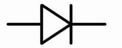
How do you know if your battery charging system is working? Check your battery voltage with the bike turned off. Start the bike. Check the battery voltage with the bike running at 1500 RPM or more. The battery voltage should now be higher that it was...and ought to be somewhere between 13V and 15V. If it is not, and particularly if your battery voltage is LOWER than it was with the bike turned off, your charging system has taken a powder. Now you need to figure out what is wrong with it. 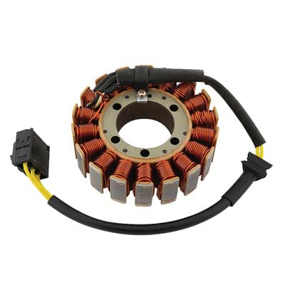 Typical Motorcycle Stator Typical Motorcycle Stator One fun thing about motorcycles is that the charging system (which you would just call "the alternator" on your car) is broken into its two major components, so you can look at them (and repair them) independently. The first part, the Stator (so named, I think, because it STAYS still while magnets spin around it) is simply (usually) three coils of wire that are located very near one or more magnets attached to the engine, so that when it is running, the magnets spin by the coils, inducing an electric current within them. (Yes, Virginia, that is how almost all the electricity you have ever used is made. Coils of wire are passed through a field of magnetic flux, causing the electrons within the wire to get excited and go flying off to some atoms further down the wire that are not quite so excited.) As you can see in this photo, the three coils are artfully arranged so that you would be unlikely to guess that there are three of them, but we know there are three and only three because there are three yellow (typically yellow) wires connected to the lot of them. How that works out will become clearer as we move on... The second part (Have you already forgotten there is a second part? I would have.) is the Regulator. The Regulator, as you might well imagine, regulates the voltage produced by the Stator. Because they are attached to the engine and the engine runs at wildly variable speeds, the magnets induce wildly variable current in the Stator, which is seen as wildly variable voltages on the output connector of the Stator (the three yellow wires). What is worse is that the Stator is producing AC current (alternating current) while your motorcycle, and notably your motorcycle battery, operates on DC current (direct [unidirectional] current). So when we call that second part of the charging system "the Regulator" it is shorthand for what it really is, which is a Rectifier-Regulator. What is a Rectifier? It is something that fixes (rectifies) something else. In this case, the "fix" is that it prevents electricity from flowing backwards. It converts AC current into DC current. In most cases, it is desirable to make use of both the forward and backward energy a Stator provides. When this is done, the circuit that routes Positive and Negative (forward and backward) current flow, so both get sent out in the forward direction, is called a "full-wave" Rectifier. And that is what is being done inside most motorcycle Regulators (a.k.a. Rectifier-Regulators). Just to make matters a little more confusing, when someone says "Rectifier" they may be referring to the entire gizmo that plugs into the bike, or they may be talking about a single-junction semiconductor device with two wires on it. Although the antiquated term for such a device may be "rectifier", for clarity, such a device is usually called a diode. And a module that accomplishes rectification, which is built using a number of diodes, may be called a Rectifier. The schematic symbol for a diode is shown below. The message in the image is very literal. A diode allows current to flow in the direction the arrow (the triangle) is pointing, and the wall (the vertical line) blocks current that might try to come in from the right. If you went out and bought one diode off the shelf, it might look a lot like the cylinder with the white stripe shown below. The white stripe corresponds to the vertical bar in the symbol drawing. It shows where current cannot enter the diode.
The several diodes in a Rectifier-Regulator convert the AC current produced by the Stator into DC current...but by themselves do nothing to make sure that the very high voltages produced by the Stator when the engine is at high RPM, voltages that can exceed 75 volts AC, do not fry the electronics on your bike or fry your "12 volt" battery. That job is handled by the other half of the Rectifier-Regulator (often simply described as "the Regulator"). Exactly how voltage regulation is done is beyond the scope of this post, and it may be done is several different ways, depending on the preferences of the folks who designed the charging system, but in the end, the Regulator will prevent the net DC voltage seen by your battery to be no more than about 15 volts. Typically "charging voltage", the voltage seen across the battery terminals while the engine is at 1500 RPM or more, is going to be around 13.5V to 14.5V DC. That is enough to make sure that current flows INTO the battery, rather than out of the battery (charging, rather than discharging). A good, ordinary lead-acid battery will show about 12.4V to 12.6V DC when it is charged and resting, so hooking a battery to a voltage source that is higher than that will charge the battery.  Typical Motorcycle Charging System A Typical Charging System Schematic This is a circuit diagram of a typical motorcycle charging system. The lines in the drawing are wires and when you see a round dot printed on top of the intersection of two lines, two wires, you know that those two wires are connected to each other. (Line crossings without a dot do not represent an electrical connection.) You can also see six diodes inside the Regulator-Rectifier module. The Stator is show as three coils of wire on the left side of the drawing. One end of each coil is connected to another coil and the loose ends are connected to the diodes in the Regulator. FYI - On many bikes, the three wires that run from the Stator to the Rectifier-Regulator (a.k.a the Regulator) are bright yellow. Notice that each coil of wire in the Stator is connected to a dot between two diodes. Notice that the diodes are all pointed UP, showing that all the current flows toward the positive (+) connection of the battery...and on to other components of the bike via the main fuse and the main power contacts in the ignition switch. Notice that each wire from the Stator is connected between two stacked diodes, so that each pair of diodes does "full-wave rectification" of the current coming from each coil (each "phase") of the Stator. The three coils of the Stator and the three pairs of diodes shown, along with the voltage regulating mechanism depicted by a regulator box and three switches (which are actually some transistors and other stuff) are the essential elements of what is known collectively as a "Three-Phase Charging System". WHEN THINGS GO WRONG There are three main functions in the charging system; production of electrical current by the Stator, rectification of the current by the diodes, and regulation of the voltage by the regulator circuits. Any of these three sections can fail or all of them can fail...and they can fail open (fail by disconnecting) or they can fail short (they can pass current to an unregulated degree or along an unsuitable path).
Testing the Stator coils is very easy. Unplug the Stator from the bike and measure the resistances between the three yellow wires...and between each yellow wire and the frame of the bike. There should be NO current flow from any Stator connection and the bike frame (a.k.a. Ground), and the resistance seen between any two of the three Stator wires should be roughly equivalent...and pretty darn low...probably near 1 ohm. (But whatever DC coil resistance may be, the main concern is that they be about equal, say within 10% - 20% of each other.) If any Stator lead is shorted to ground (to the bike frame) the Stator is bad. If any two Stator leads show a dead short (~zero ohms) or leaks to the bike frame, the Stator is bad. Testing the diodes in the Regulator-Rectifier is more complex conceptually, but not in practice. The Regulator needs to be unplugged from the bike completely. The DC wires (often red and black) and the AC wires (usually three yellow wires) need to be disconnected from the bike's wiring harness. Then each phase can be tested. Sidebar: A Multimeter with a Diode Test Function I use a very nifty multi-meter (that was not at all expensive) with some very useful functions, including Diode Test Mode. Note in these photos that the control knob is set to measure resistance but the meter is reading volts (!). That is because the way a multi-meter always test resistance is to send out a know voltage from inside the meter and then look at what comes back. Diodes have a very particular characteristic compared to other devices like resistors and light bulbs. While resistive devices will show a larger and larger voltage drop across their terminals as voltage is increased, the voltage drop across a diode will stay nearly constant, despite the fact the diode is conducting more and more current flow as the applied voltage increases. In Diode Test mode, the meter reports the voltage drop it is seeing across the device being tested.
Regulator Diode Testing Connect your diode tester to a Stator wire and check for diode current flow through the positive and then the negative terminals of the DC output voltage connector. One of the DC terminals should show current flow...only one. Then reverse your diode tester connections and check the same points. Now the OTHER DC terminal should show diode current flow while the one that flowed before should indicate blocked flow.
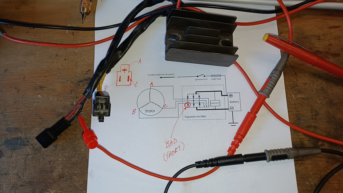 Results from an actual Regulator Assembly Test (which showed one shorted diode) In the example shown here, current was found to be flowing from terminal A on the Stator to the positive (+) DC terminal of the Regulator (which it should) AND to the negative (-) DC terminal of the Regulator (which it should not). That measurement proved that this was a bad regulator. It must be noted that testing the diodes in this manner CANNOT conclusively prove a Regulator is good. Such a test can only prove that a Rectifier part of the Regulator is bad. The diodes could all be just fine and the regulating circuits themselves could be bad, resulting in bad system voltage on the bike. However, in this case, testing revealed at least one bad diode inside the Regulator assembly, so it is a gonner. Additional Tests
Once you have determined the major components of the charging system are functioning with the bike turned off, there are other tests you can do with the bike is running. With the engine running AND the Stator unplugged from the regulator, check AC voltage between each of the three Stator output terminals (Three measurements...on the drawing above would be point A to B, A to C, and B to C). The voltage seen at any given engine RPM should be about the same for each measurement (because the coils and magnets are the same for each phase). You may see nearly 100V AC on these terminals, so be careful. Anything much past 24 volts can be noticeable and 48V and up can hurt...and can certainly be deadly. Watch yourself. This test is particularly useful if the Stator is wounded and only shows a short at higher voltages or only shows an open when it is being vibrated by the motor. The key for each of these measurements is that under the same conditions, they should match each other pretty closely (say +/- 10%). Needless to say, if you see bad results in these tests, you have a bad Stator and need a new one. Repeat the measurement of the AC terminals with the Regulator plugged in. Again, each phase should be the same as another...although probably not the same voltages seen when the Stator was unplugged. Seeing generally lower voltages would be normal because the Stator is doing real work if it is plugged into the Regulator. But be on the lookout for seriously low output voltage on any phase of the Stator. A bad Regulator may collapse the Stator AC output on any or all phases. One low or high phase measurement when the Regulator is plugged in, despite seeing uniform AC voltages on each phase of the Stator when the Regulator us disconnected, suggests a bad Regulator. With the Stator and the Regulator connected normally, check the DC output voltage of the Regulator with the Regulator connected bike. For reference, check battery voltage first and keep that number in mind. Then start the bike and check battery voltage while it is running. Whatever voltage you see at idle should increase somewhat as you increase engine RPM but should stop climbing once it gets into the 14.5V to 15V range. If, when you are at 1500 RPM (high idle), it is not at least equal to the battery voltage you measured when the engine was not running at all, something is wrong (perhaps a bad Regulator, but possibly a bad Battery). If DC voltage keeps climbing past 15V when you increase RPM, STOP THE TEST before you blow bulbs or worse on your bike. And get a new Regulator. Disconnect the DC output of the Regulator from the bike and check Regulator output voltage while the bike is running, again slowly increasing RPM, checking to see how much output voltage increases as engine speed increases. If it is too low to charge your battery (say, less than 12.6V DC) or too high (say over 15V DC), you have a Regulator problem. Comments are closed.
|
Categories
All
Archives
January 2024
|
 RSS Feed
|
© WrenchMonster 2018
|
WrenchMonster™ is a Division of DemonLite, LLC.
|