|
It would seem the obvious answer would be "Get a voltmeter and test it." Sadly, that doesn't really work. A quick voltage test can be very deceptive. Unless you get more data, you are about as likely to draw a bad conclusion as a good one. A good battery can give a lousy voltage reading simply because it needs to be recharged. But a bad battery can show a perfectly good voltage, but completely fail to turn your starter motor. How can this be?! Welcome to WrenchMonster's basic course on electricity. Let's start with an analogy. Electricity is like water. It has pressure (voltage) and volume (amperage). Everybody knows about voltage. High voltage is dangerous. Touching a high voltage wire hurts and might kill you. But the volume aspect is not obvious because we cannot see electrons. Amperage, the volume feature of electricity, relates to the number (volume) of electrons that are going through the wire. A voltage measurement tells us how hard the electrons are being pushed. An amperage measurement tells us how many electrons are going through the wire. It is easy to imagine a water hose with giant pressure behind it...and a sprayer nozzle on the end of the hose that is just a pinhole, so only a tiny amount of water actually comes out. It may come out hard and fast, but if you point it at a heavy object, it probably won't knock it over. On the other hand, if you have a fireman's hose, which is very fat and can carry lots of water...and it has a nozzle on the end that is MUCH larger than a pinhole, you can bet turning that hose onto a heavy object (say a cement block sitting on the sidewalk) will knock that concrete block and roll it down the street...even if the pressure behind that water is no higher than is behind your household tap water (which is exactly the case for all the fire hydrants that line our streets because they are fed by the same water mains that are connected to our houses). Electricity works the same way. Volume matters, whether it is gallons per second of flow or electrons per second of flow. When measuring electrical circuits, we need to know about voltage, amperage and RESISTANCE (how much the flow is being held back). The size of the nozzle at the end of the hose does matter. We need to know how hard it is for the electrons to get through the circuit. There are lots of ways to resist the flow of electrons. A switch breaks the circuit entirely, like a valve cutting off the flow of water. The voltage, the pressure, is still there, but the resistance is nearly infinite, so the flow of electrons (measured in amps) goes to zero. But it is also possible to throttle the flow of electrons; to open the valve a little bit. Different materials have different resistance properties. Copper has very low resistance. That's why so much of our wire is made of copper. Carbon can pass electricity, but not very well, so we can use chunks of carbon with wires connected to each side to intentionally hold back the flow of electrons. If you've ever looked at a PC board in a computer you've seen lots of these devices, which naturally are called "resistors". And it's also true that other chemical compounds may be better or worse at passing current...including the chemical compounds in batteries. What's more, how easily the chemicals in a battery can pass current CHANGES as the battery ages...and that begins to answer the title question. The proper way to test a battery is to measure the internal resistance of the battery. Unfortunately, you can't simply set your meter to OHMS (the scale we use to describe how much something resists the flow of electricity) and connect it to the battery. All that will do is blow the meter protection fuse in the meter...or burn up the meter if it doesn't have an internal fuse. To figure out the internal resistance of a battery we need to measure other things and then use some math. Ohm's Law: Volts = Amps x Ohms which is also written in electrical shorthand as V = I x R Yes, there was a Mr. Ohm who figured out this math. And because of the magic of algebra, we can express Ohm's Law three different ways... V = I x R I = V / R R = V / I V means Volts, R means Resistance (measured in Ohms) and, I (a capital "i") means Current (measured in Amps). Therefore, any time we know two things about electricity flowing through something, we can calculate the third one. To figure out the internal resistance of a battery, which we cannot measure directly, we need to measure the things we can measure, and then use math to calculate the internal resistance of the battery. One of the most important things we need to measure along the way is the voltage the battery can hold across a known load (a resistor of known resistance that’s connected to the battery terminals). Because of the work of another smart guy, Gustav Kirchhoff, we know how electricity works in a complete circuit. In a series circuit (one where the electricity flows in a single loop from the battery, to a load resistance, and back...without branching off and going elsewhere) we know that any push caused by the battery is balanced exactly by the push back offered by the elements in the circuit. So, if a “push” is a rise in voltage, then the “push back” is a drop in voltage. In a series circuit, for every rise in voltage as we go around the loop, in the end, when we get back to where we started, there must have been exactly the same amount of voltage “drop” (a loss of electrical pressure) by the time we get back where we started. Or to put it another way, all the rises and drops (which we express as a negative number) in voltages in a series circuit add up to zero. We also know the current flowing in one part of a series circuit must be exactly the same in every other part of the circuit, just like if we had a loop of hose connected to a water pump. All the water being pumped into the hose would circulate back to the intake of the pump. As long as our hose has no leaks, the amount of water in the loop of hose never changes…it just goes around and around. Same for electricity... 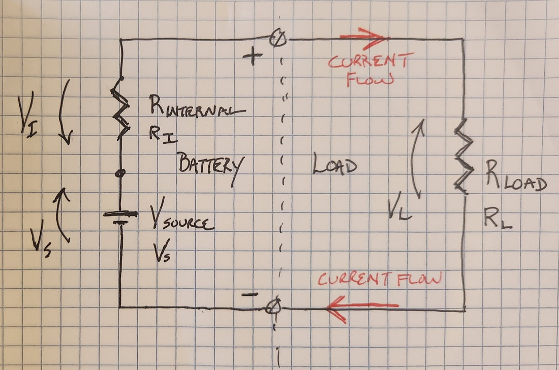 This is a picture of a typical circuit diagram. Nothing special. A zig-zag symbol represents a resistor or the resistance of an object in the circuit. The parallel lines (Vs) represent the "electron pump" inside the battery; the combined effect of all the battery chemistry in the battery that causes the push on the electrons that we measure as voltage. The screw terminals marked with (+) and (-) represent the external terminals of the battery. The whole point of this article is Ri, which is shown between the positive terminal of the battery and the voltage source inside the battery. That symbol represents the total internal resistance of the battery, which we model mathematically as if it was a single resistor inside the battery. Naturally, it’s not actually as single resistor inside the battery. Internal resistance is the net effect of all the resistive mechanisms at work inside the battery, just like Vs is net effect of the battery chemistry trying to push current out of the battery. We lump those push and resistance effects into these two circuit elements mathematically to simplify the calculations we need to do. (And it really works!) The voltages in this diagram are marked as Vs (the Source Voltage), VL (the voltage drop across the load resistor connected to the battery terminals), and Vi (the voltage drop across the internal resistance inside the battery). FYI - The arrowheads convey where the voltage is higher, meaning if you were able to connect a voltmeter at the dot between Vs and Ri, you would see a higher voltage at the dot than at the other end of Ri...or to put it another way, if you walk from the negative terminal of the battery, clockwise around the circuit, voltage would be the highest at top of Vs, would drop as you crossed Ri and would drop further as you crossed RL. That is what we mean when we talk about Kirchhoff's Voltage Law (the voltage rises and drops in a series circuit must sum to zero). We express voltage drops in an equation as a negative number so, Vs - Vi - VL = 0. In a series circuit, if we measure the voltage across the load resistor, and if we know the resistance of the load resistor, we can calculate the number of amps of current that are flowing through that resistor. And because this is a series circuit and no electricity is leaking out to other places, we know that same number of amps are flowing through the battery too. If we know the value of Vs, VL, and we know how much current is flowing through the battery while the load is connected, we can calculate the internal resistance of the battery. But how do we measure the internal “push” of the battery? How do we measure Vs? The test setup to measure the Vs of the battery is shown in this next diagram. It is the battery sitting by itself with nothing connected to the terminals. The voltage the battery can produce with nothing connected is known as Open Circuit Voltage, or the No-Load Voltage of the battery. 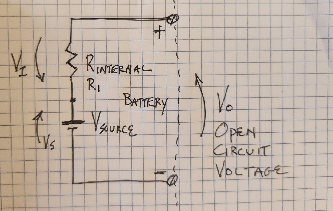 If there’s nothing connected to the battery, we know there’s no current flowing through the battery...and that means no current is flowing through the internal resistance of the battery. Because V = I x R, we can be sure that if the I term, amperage, in the equation is zero, no matter what the value of R, zero times R is always zero. So, if the battery can produce Vs (source voltage) internally, and none of it is being dissipated across Ri, meaning Vi must equal zero, then what we can see at the output terminals of the battery, Vo, must be equal to Vs. Which is to say, we can actually measure the value of Vs directly at the terminals of the battery, as long as we don't connect anything to the battery. Nothing to it, right? Except we need to connect something to the battery to measure its voltage. Here's the good news. Voltmeters are specifically designed to present a VERY high resistance to any circuit they touch. The whole point is for the meter to leave the circuit under test undisturbed. The input resistance of most voltmeters is millions of ohms, which is about as close to electrically invisible as you can get. The current that goes into our voltmeter is so small we can ignore it in our calculations. So, at the top of this article I said just connecting your voltmeter to your battery would give you the wrong answer...and that is true, depending on what answer you are trying to get. If you want to know the Vs of the battery, it’s exactly the right thing to do. But the Vs of the battery is only part of the story. What we really want to know is "What voltage can the battery maintain with an actual load hooked up?"...like the starter motor for example. And that’s where the value of Ri becomes so critical. Have you ever seen a bike or a car that has all the lights come on when you turn it on, but they all go dim or out when you hit the starter? Your lights do not require very much current to light up, maybe one or two amps of current. LED lights need even less. A bad battery (or a poorly connected battery) is able to produce enough voltage, under that light load, to make things work. But as soon as you put a heavy current demand on the battery, 100 amps or perhaps more, by connecting something like the starter motor, the output voltage of the battery collapses; the starter motor will not run and the lights go dim. That is all because of the Ri, the internal resistance, of the battery. Let's suppose for the moment that your starter motor requires about 10 volts and 100 amps of current to spin with conviction (those are not unreasonable numbers for a motorcycle starter motor). We know that if the motor (RL) is pulling 100 amps, then 100 amps must be flowing through the battery too, including Ri, the internal resistance of the battery. Let's say the battery we are using shows 12.6V of open circuit voltage, which we now know means the value of the battery's Vs is 12.6V. If a starter needs 10 volts at 100 amps, then the internal resistance of the battery must not use more than 2.6V when the starter is connected for us to get a goods spin from the motor. We now have all the data we need to calculate the how much resistance Ri can have before the voltage left for the starter motor falls below acceptable limits. 2.6V / 100 A = 0.026 ohms, otherwise known as 26 milliohms or 26 thousandths of an ohm...and that’s not much. But in this example, where we are trying to spin a 100A starter, it is as high as the internal resistance of this battery can get and still produce the voltage and current needed for this starter motor. In this example it is low enough to spin that starter properly, but if the internal resistance goes any higher, the voltage it dissipates will go higher and the output of the battery will drop below 10V, starving the starter motor of the power it needs. But suppose the Ri of that same battery was 0.100 ohms...only 4 times higher. In that case, a 100A demand on the battery would result in an internal voltage drop across the internal resistance of the battery of...100 amps x 0.1 ohms = 10 Volts. That means 10 volts of the 12.6 volts that battery can produce are stuck inside the battery and we would only see 2.6 volts on the output terminals of the battery. That, my friend, is a very bad battery. So that is why Ri matters and how an Ri that is too high can make what may look like a good battery with a simple voltmeter test, proves to be completely useless when it comes to starting your machine. But we need to get back to the original question: "How can I tell if my battery is good?". The answer is a two-step process: 1. Test it with no load; nothing connected but the voltmeter and record Vs. 2. Test it again with a load of known value; a test load, and record VL. To get valid results, it is best to use a pretty heavy test load, so the battery is really having to push some current when it is under test. That’s the idea behind the big clunky battery testers sold at the auto parts stores, like this one, for example.
Ok, back to the problem at hand. We have a voltmeter and now we have a test load of known value. We are ready to figure out the internal resistance of our battery. Let's review the whole process from the start... 1. We measure the Open Circuit Voltage of our battery, which we know is equal to the Vs of the battery...and let's say we measure 12.6 Volts. 2. We measure the resistance of our test load, and find we have a 0.5 Ohm resistor inside the tester. 3. Now, we connect the test load to the battery (not for too long...20 seconds or so) and we measure the voltage on the battery terminals WHILE THE LOAD IS CONNECTED, and let's say we read 12.4 Volts on our voltmeter. 4. Now we have all the data we need and we can do some math. Vs is 12.6V and the voltage measured across the load, VL, is 12.4V, so the missing 0.2V must be across the only other element in the circuit, which is Ri, the internal resistance of the battery. The equation for that is Vs - VL = Vi = 0.2V (so says Mr. Kirchhoff). We know the load resistor has a value of 0.5 Ohms and the voltage across the load is 12.4V while connected to the battery, so the current flowing through the circuit (which is the same through all components in the circuit, including the internal resistance of the battery) while the test load is connected is VL / RL = Test Load Current = IL, which in this case is... IL = 12.4V / 0.5 Ohms = 24 Amps And with that, at last, we have the last piece of the puzzle we need to figure out internal resistance, Ri... Ri = Vi / IL = 0.2V / 24A = 0.0083 Ohms But...is that good or not? It depends on what the Ri of the battery was when the battery was new. A little more math allows us to figure that out. Each battery has a CCA rating (CCA = Cold Cranking Amps). It’s a rough indication of how much current the battery is designed to produce in cold weather, while maintaining an output voltage of about 7 volts (when it’s hard for batteries to deliver power). Car batteries usually promise hundreds of Amps in freezing weather, but motorcycle batteries are smaller and normally deliver less, typically 100 to 200 CCA. Let's say the one we have been testing in this example has "120 CCA" stamped on the outside. Because we’re probably not going to put the battery in the freezer overnight before we test it, it’s going to be hard to compare our test results to the battery CCA spec, but it’s safe to say we can consider the CCA rating of the battery an absolute minimum amperage we should expect to see from a battery while sitting our garage on a spring day...and here is the key...the CCA rating of the battery, more or less, is the minimum amperage we should see when the battery is producing at least 10V at "room temperature" on the output terminals. Note: Different standards organizations have slightly different test procedures for testing the CCA of a battery, but they are all pretty similar to each other...and close enough that we can ignore those differences in this discussion. The reason I cite 10V at room temperature vs. 7.2V at -18 degrees C (one of the CCA test standards) here is that the battery should perform 20% - 30% better at warmer temperatures...and it’s a good ballpark number for the least voltage we want to see on our starter motor when we’re trying to start the bike, and therefore a good cutoff voltage for evaluating whether the battery is minimally acceptable. Because your bike's designers selected a battery with a certain CCA rating, if we use it as our guide, we know we have scaled out expectations for the battery to roughly fit the needs of our bike. If we expected output current performance that matched a car battery, every motorcycle battery would look bad. (And that is why the good/bad scale on that cheap battery load tester we cited earlier may not be valid for testing your motorcycle battery.) Because there is no practical way to load a battery down in the shop so that it produces exactly 10V, we go back to using math... Again, we still know Vs of our battery is 12.6V. If we – hypothetically - load this battery down so hard that it can only produce 10V on the output terminals, how much current must it be producing at the time? We already have all the data we need to figure that out... If Vsource is 12.6V and the hypothetical Vload is 10V, the voltage across the internal resistance of the battery in that case would be 2.6V. We already figured out internal resistance is 0.0083 Ohms. In that situation, how much current must be flowing through the internal resistance of the battery? 2.6V / 0.0083 Ohms = 313.25 Amps! Wowzer! That is WAY more than the 120 Amps the sticker on the battery says it must be able to produce. Awesome. The Ri of this battery is much lower that is needs to be to meet the 120 CCA spec. This is a very good battery. What might a "bad" battery look like? Suppose we had that same 120 CCA battery, but it showed a Vs of 12.3V when we did out open circuit voltage test, and after we did know-load testing, we did our math and figured out it has an internal resistance of 0.0250 ohms. We can do the math for the hypothetical load with these numbers the same way we did before... Voltage across the Internal Resistance = 12.3Vsource - 10Vload = Vi = 2.3V then, 2.3Vinternal / 0.025 ohms internal resistance = 92 Amps Bummer. that’s not so great for a battery that’s supposed to have a 120 CCA capability, particularly since we didn’t do our testing under the freezing conditions of a real CCA test (which would have resulted in us measuring an even higher internal resistance, causing an even worse current output when the battery is loaded down to 10V). Even though we proved this battery can ALMOST get to its rated 120A @ 10V output spec, it did not make it, even in warm test conditions. This battery has got to go. So that's the story. You can test your battery. Yes, you do need a voltmeter, but that’s not enough. You also need a known-value test load and some math skills. Or you can buy a battery tester that actually does all that work for you and tells you the internal resistance of your battery when it is done. Something like this one... 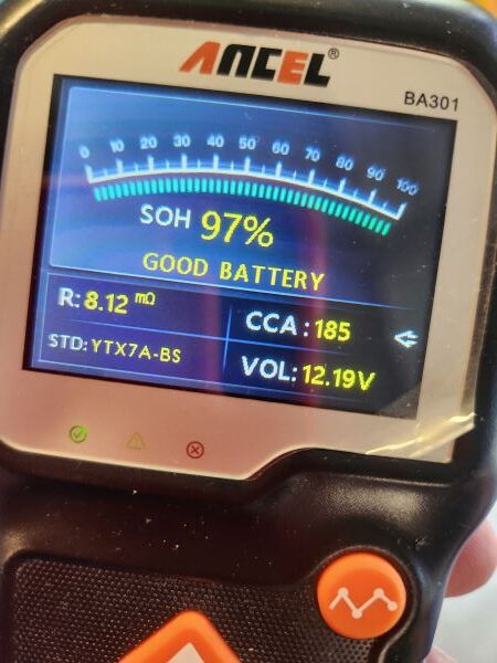 This little tester is made by Ancel. It, and similar units from other vendors, can be purchased for less than $40. You tell the tester the model number of the battery you're testing (or the CCA of the battery you’re testing) and it does the testing and the math for you. It tells you the internal resistance of the battery and gives you a broad assessment of the battery's "State of Health" or SOH.
This picture shows an Ancel BA301 tester connected to a battery for testing. The battery is currently showing an Open Circuit Voltage of 12.19V (In this case they are calling it Open Loop Voltage, shown on the display as "VOL") and the measured Internal Resistance of the battery is shown as "R: 8.12 mohms (i.e. 0.00812 ohms or 8.12 milliohms). And the display shows that the tester evaluated on the basis of it being rated for 185 CCA (Recall our earlier discussion about CCA. If we had told the tester the battery under test is rated for 600 CCA, despite measuring the same 12.19V VOL and 8.12 mohm Ri, the tester would say we have a bad battery.) Pretty cool, huh? By the way, this battery should be recharged to see if it will come up to 12.4V to 12.6V. If it does, it will probably show an even better internal resistance. The moral to that story is that you can’t expect to get reliable test results from a discharged battery. To do a good test, charge it up, use it for a few seconds (hit it with a test load, or hit the starter button for a sec, or turn on the headlights for 10 seconds) to burn off the deceptive “surface charge” and then do your testing. It has happened to us all. The engine in your bike / car / truck / boat / lawnmower / etc. was running just fine and all the sudden it is missing, coughing, sputtering, shuddering, stalling out, and maybe even now it won't start, even though you have lots of gas and the engine spins up normally when you hit the starter...it just won't start or runs like crap. What the heck? To be fair, there are LOTS of reasons a properly running engine can suddenly go bad, but this posting is about one of the most common reasons: Bad Gas...or more accurately, water in the gas tank. So when are you justified in thinking the problem may be bad gas when your engine suddenly starts to run badly?
Why is water in your gas a problem? Gasoline burns. Water? Not so much. A little water in your gas can make the engine run badly. A big slug of water getting into your fuel system can bring your engine to a sudden and ignoble stop. But how does water get into your gas tank? There are lots of possible ways. The ugly ones all revolve around the fuel having been handled badly before it got to you. Perhaps a storage tank had a leak or a loose lid that let rainwater get in. But that sort of thing is very rare. The most common way for water to get into gas tanks is for it to come in as humid air. Air can hold more water when it is warm than when it is cold. That is why the weather report always talks about Relative Humidity. The RH is tells us how much water vapor is dissolved into the air relative to how much it can hold at that specific temperature. So if if an air sample is at 50% RH at a specific temperature, it will have a higher RH at a lower temp and a lower RH at a higher temperature. The actual amount of water in the air sample will not have changed. What changes with temperature is the air's ability to hold that water vapor in solution. And if you cool it enough, you eventually reach the Dew Point for that air sample, the temperature at which the water vapor starts to condense out of the air, i.e. the water vapor begins to turn into liquid water. If you capture a dry jar full of air outdoors on a warm day, close it up tight, bring it inside and stash it in your refrigerator, when you come back the next day (after the air has gotten nice and cold inside the jar) you will find some liquid water inside the jar. As the air cooled it could no longer hold the water vapor, and the water began to condense (water vapor converted back to liquid water). Whatever the relative humidity of the captured air might have been outside, as the air cooled, the relative humidity inside the jar got higher and higher until it got to about 100% (meaning it became as humid as it could be before the water vapor condensed into liquid water in the jar). The more water vapor that was dissolved into the air sample to start with (the higher the RH was when you captured the air), the easier it will be to get the water to condense out as the temperature of the sample falls...and the more water will end up in your jar. This all matters because most fuel handling systems, at least briefly, allow air to get in now and then. Once air is in a storage tank, gas can, or fuel tank, it becomes possible for the moisture in that air to condense into your gas tank. So why are big weather changes harbingers of bad gas? The easy one is a cold snap. Hot humid air got into the tank back when it was warm outside, then a cold night comes around and the humid air in the tank condenses into water as the tank cools. But it is also possible to have a fuel storage tank that has been cold that gets exposed suddenly warmer and more humid air. The warm humid air gets into a cold tank and, bingo, the cold fuel chills the humid air and once again there is water in the tank. Generally, the onset of winter is more likely to cause problems, but springtime can also mess with our fuel supply. Still, why is a little water in a gas tank a problem? What harm can a little water do when mixed with gallons of gasoline? The problem is that they do not mix. Water sinks to the bottom of a tank filled with gas or oil. Here's a sample of some contaminated fuel. The line of separation is the natural result of trying to mix gas and water. The water is the bottom layer. 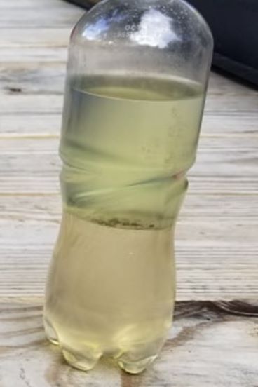 Once water is in the tank, it tends to go to the bottom, which of course is where the fuel pick-up is located (so you can get the last little bit of gas out of your tank as you get near empty). Now, the sample shown above is a badly contaminated sample. Your tank may only have a tablespoon full of water in it. And it may be sloshing around as your vehicle moves so that the little slug of water only rolls by the fuel pick-up now and then, and only briefly at that. That can be enough to make your engine shudder, buck, and cough...and if you are unlucky enough, the fuel pump may suck up enough at one time to stall your engine. So, what to do? We could try to dump your gas tank or suck out the water, but both are usually impractical. Fortunately, there is a better option: Mix the water with something that will burn. Gasoline is not the only flammable liquid in the world. Some liquids, like alcohol, for example, mix beautifully with water and are also flammable. But the liquid I prefer to use is Berryman's B-12.
The Berryman company does not pay me a nickel to say nice things about their stuff. This is just the straight skinny. B-12 is GREAT. It is a super fuel system cleaner, but it is a spectacular water dispersant. I carry a can of B-12 with me in each of my vehicles...because you never know when you are going to get a tank of bad gas...and if you do, B-12 is the almost instant cure. And when you can buy it for less than $5 a can, it is absolutely the cheapest miracle cure available on the planet. And yes, I run a can through each of my vehicles once or twice a year just for good measure.
Notice that you are seeing a can of B-12 LIQUID. They also sell B-12 in spray form for spot cleaning fuel system components. It is great, but get the liquid for dealing with bad gas. So, when the day comes that you get the dreaded sputter / cough / stall routine from your engine after a fillup, dump a whole can of B-12 into your gas tank. Give it a few minutes to mix with whatever is in your tank, and then try to go again. In a car, the tank is usually in the back and the engine is usually in the front, so the pipe that connects them can be a bit long. Don't be too dismayed if it takes several attempts to get the improved fuel up to the engine. As a rule, fuel does not flow unless the engine is turning (turning, even if not necessarily running). The moral to that story, by the way, is if you notice your engine starting to run rough after a fill-up, don't wait until it dies to put in the B-12. Put it in right away. The problem will clear much more quickly and easily if the engine is running, even running badly, than if it is not running at all. And then go get another can of B-12 at an auto parts store as soon as you can and stash it in your trunk for the next time you get bad gas. So that's it. Generally, jumping to conclusions when something goes wrong is a bad idea. As a rule it is much better to figure out what has gone wrong before attempting a cure. But in this case, a can of B-12 is so cheap, and putting it into your tank is so easy, even if it fails to fix your problem, you have lost very little time and money. So if you have the least suspicion you are a victim of bad gas, go for it. It can't hurt and it may well be the cure. There are a lot of videos out there about how to load and strap down a bike. Most of them are dead wrong. The best advice is "Don't", as in, "Have it towed by a qualified motorcycle towing service." As you may have already noticed, on my website I recommend one such service here in Austin, https://ATXBikeTow.com However, if you are like me, and have access to a tow vehicle (a car, SUV, or truck with a hitch) you will probably ignore that advice and do it yourself. So, for all the stubborn SOBs like me, here are some tips for how to trailer your bike without hurting it or yourself. FIRST, never try to put a big bike (anything bigger than a 125) into a pickup truck. The load bed is too high, so your loading ramp is going to be too steep, and your bike falling from that high is likely to do thousands of dollars of damage to the bike...and more to you when you try to save it. Just don't. Yes, some folks have gotten away with it...but so many have not. Conversely, DO use a trailer, preferably a motorcycle trailer. There are lots of different types of motorcycle trailers out there, but the single most important characteristic they all share is some sort of feature that helps restrain the front tire of the bike. The simplest is indentation in the front of the trailer like this... 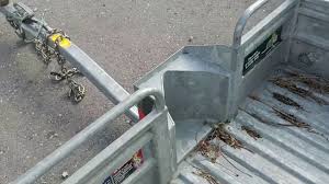 That simple pocket in the front of the trailer really helps keep your bike where it belongs. There are other mechanisms out there, all broadly described as a "Motorcycle Wheel Chock". Most can be added to the floor of an ordinary flatbed utility trailer or mounted inside an enclosed trailer. But the truth is, even some blocks of wood nailed to the trailer floor on either side of the front wheel, so the front tire cannot scoot side to side as the trailer bounces around, can be a big help. So don't feel like you need to break the bank to get the job done. But back to trailers vs. pickup trucks...the key issue is that a trailer is going to have a much lower load bed than a truck and that makes the whole operation MUCH safer. One of the best deals in motorcycle trailering is renting a motorcycle trailer from U-Haul. They have great little trailers and they rent them pretty cheap. 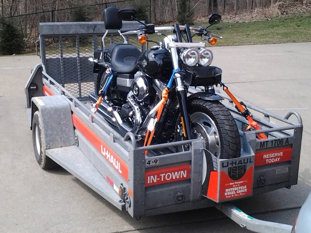 How to Strap Down a BikeThis is the subject that most often comes with bad advice. Strapping down a bike is done wrong so often that it is hard to find examples of it being done right. The picture above of the bike in a U-Haul trailer is a great example of the WRONG way to strap down a motorcycle for towing...or onto a motorcycle lift for repairs. The approach is the same either way. Note in the photo above that the tie down straps are connected to the forks. That is good, as far as it goes. That is way better than tying the straps to the handle bars...but it still is not right. The problem is that the straps are tied on above the lower half the the fork legs. The upper half the the fork legs move up and down when the bike hits a bump because there are springs inside the fork legs. That is great for your butt when you are riding the bike. You get a nice comfortable ride and your tires stay stuck to the road and make it easier to maintain control over bumpy surfaces. But the fact that the upper parts of the bike will bounce up and down when you hit bumps in the road makes them a TERRIBLE place for the tie down straps. Here's the deal. If you tie off above the springs, every time your bike bounces DOWN, the straps get loose, and that's when your bike falls over in the trailer. Not good. And when the bike bounces back up, the straps can get so tight, so suddenly, that metal parts (like handlebars) can be bent and plastic parts can be broken. Some folks will tell you the way to address that problem is to strap it down REALLY tight, so the suspension is compressed so far the bike cannot bounce. That is also bad advice. The correct way to tie down a bike is to attach the straps below the suspension. You can attach to the wheels / tires, to the axles at the base of the fork legs or the swing arms (rear wheel), or to the lower fork legs. As long as the front wheel of a bike is tied down tight to the trailer, the bike cannot fall over and there is no danger of damage to the suspension or the handle bars. If tying down the rear wheel makes you feel better, do that too. (I almost always do.) Yes, it is true that the main body of the bike will bounce up and down when the trailer hits bumps, but the bike is designed to bounce up and down when it hits bumps. No problem. As long as the wheels stay firmly planted the bike will stay put. There are some tie down accessories that can make the job a little easier, but none of them are necessary. One example is a purpose made harness for the wheels themselves. They are usually used on rear tires because the front wheel is usually too easy for a wheel strap to be necessary. But there are a number of valid ways to get the job done. Here are a few... The bottom line is, if the wheels are tied down tight, the bike cannot fall. You cannot do better than that. If you want to watch a GOOD video on the subject, watch this guy.
Tide Down Demo or How to avoid going insane trying to get the same route on your phone and your GPS.  1. Preface
There is a method that can keep the routing madness under control when trying to cause common GPS routing solution generation with REVER, Garmin GPS and Goldwing (2019+), or for that matter, any other GPS routing platform. Without observing some very specific procedures and settings in each platform, a common GPX waypoint listing can produce wildly different routes, leading to enormous confusion in a group ride where different riders are using different GPS systems. The language chosen in the preceding paragraph speaks to the central principle that must be recognized in any effort to produce common routing results across multiple platforms, to wit, each GPS platform makes its own decisions about how to convert a list of waypoints (imported from another platform via a GPX file). Moreover, most platforms offer a set of routing decision biases (or Routing Options) that the user can select to influence how that platform produces a route (e.g., users may choose “Fastest Route” or “Curvy Roads” or “Avoid Highways”) And, of course, each platform makes its own decisions about how to implement a routing bias, even if one or more other platforms use exactly the same terminology to name the route bias (i.e. “Avoid Highways” on one platform is not guaranteed to have the same effect on a different platform). So… The objective being addressed here is being able to generate a route in one platform and then export it to other platforms and get the same route on each of them. The fundamental methodology is to create a route in one platform, export it to a different platform, compare the results, and IF THEY DO NOT AGREE, add waypoints to the route IN THE ORIGINAL PLATFORM and re-export the route to the target platform, to see if route agreement has been achieved. Eventually the original platform route will have enough waypoints in it to force the target platforms to produce a matching route. (Yes, this means the original platform has a bunch of waypoints in it that are superfluous on the original platform…but that is ok. They do not hurt the originating platform routing performance. As a practical matter, it is important to set each platform to a routing mode that approximates that used on the originating platform. A lot of frustration will erupt if the originating platform is set to “fastest route” and disallows unpaved roads…but the target platform is set to generate the shortest route and allows dirt roads. It must also be noted that the map databases that each platform use for route generation may disagree about map facts. (e.g., one may identify a road as unpaved, when satellite or “street view” in another platform makes it clear the road in question is, in-fact, paved). These sorts of disconnects are very difficult to overcome and may force you to simply abandon plans for that road and take another one (if you want the various platforms to agree on the route). The “Why So Many GPS Platforms?” Sidebar I can tell you why I use more that one platform. The #1 reason I always travel with a “REAL” GPS unit, despite how much I LOVE cloud-based navigation solutions like Google Maps or REVER, is that even though those platforms support downloading map data so that your cell phone continues to provide routing instructions even when you ride into a massive cell service dead zone, if you are in a dead zone and need to generate a new route (e.g., your riding buddy has had a wreck and you need to get to a hospital), the cloud-based smartphone navigation tools simply cannot do any route generations tasks without a network connection. Route generation is always handled by the server at the other end of the network connection. Yes, it is true, there are some smartphone/tablet navigation apps, such as Sygic (which works well in the USA, despite its decidedly European bias), that actually do local (using the phone’s processor and memory) route generation…and therefore are a suitable substitute for a “Real” GPS unit. But being a belt & suspenders kind of guy, I prefer my back-up navigation solution to be in a physically separate device so it will still work if the cell phone stops working, whether the cause is a bad cell connection or a dead battery, or because I dropped it. So, having said all that, what follows is methodology I have developed and, for the most part, like using. 2. The Tools I depend on Google Maps, Garmin Zumo and lately REVER (https://a.rever.co/). I have been a heavy user of GPS navigation since the first handheld moving map GPS was released for sale by Garmin (I still have mine.). And I can say with complete enthusiasm, REVER is, by far, the easiest motorcycle route planning tool I have ever seen, despite a little wonky weirdness in the user interface. I love it and use it to plan new ride routes at home on my computer, despite the fact the cell phone version goes stupid without a live network connection. And it must be said, the cell phone version, intended to be used while you ride, does have some pretty cool features...more if you get the paid version, notably, live weather overlays on your live route map. Despite that, the Garmin Zumo is by far the best on-bike active navigation system to use while on a ride, especially to places with spotty cell phone coverage (indeed, usually my favorite places to ride). But route planning on the Zumo is practically impossible...and doing it on the Garmin route planning PC program, BaseCamp, is just plain painful…doable, but painful. Route planning on the Goldwing Navigation System is both difficult and dumb. (Who wants to sit in the garage for hours thumbing the control buttons like it was a flip phone?!) And using the Goldwing Navigation System on the road is the worst. Nanny Attitude has rendered it unusable for anything but long hauls down hundreds of miles of straight interstate highways. A rider cannot even change the zoom view of the display while in motion! Pass. Therefore, my methodology is to generate routes in REVER and then export them (via GPX files) to other platforms, notably the Garmin Zumo, and the Honda Goldwing Navigation System (for my friends who only have the Goldwing system to back up REVER on their phones when they are on a ride). My previous first love was Google Maps, and I still use Google Maps more than any other platform on a daily basis. But Google Maps has a fatal flaw (besides going dumb without a network connection). It will not export or import a GPX waypoint listing. In the past I would develop a route in Google Maps (using the Topo map, Street View, Satellite View, and various routing options) to generate routes I could believe in, and then recreate those routes by hand in Garmin BaseCamp so I could load them into my Garmin Zumo or export them to other platforms via the BaseCamp GPX export feature (which often proved unsuccessful). So, here’s the inside scoop (not fact checked, but I believe this is true based on my own observations) … REVER is pretty obviously based on Google Maps. Both platforms seem to be working from the same database and implementing virtually identical routing algorithms (which is just me being tentative…they really look identical to me). The downbeat on this is that the OEM Goldwing (+2019) Navigation system ALSO seems to have Google Maps DNA. It is useful to note that the Honda Route Planning tool (now discontinued in favor of sending Goldwing customers to REVER) was absolutely shamelessly built on Google Maps…suggesting, at least to me, that the INDEPENDENT routing algorithms that have been implemented in the Goldwing navigation system have been intentionally designed to mimic the decisions being made by the Google Maps servers when they build a route. So…given that my personal objective has been to generate routes in one platform and then have them successfully reproduced, turn-for-turn, by my cell phone (formerly running Google Maps but now running the REVER app), my Garmin Zumo, and a Goldwing Nav System, REVER has emerged as the right choice for initial route planning and the obvious source for GPX data to be used by both BaseCamp (on the way to the Zumo) and the Goldwing Nav System. It works pretty darn well, IF you have your settings right on each platform AND you follow the baseline procedure (which is: If you see an error / route discrepancy, FIX IT IN THE SOURCE ROUTE. Yes, it seems like a time-consuming PIA…but it eliminates a ton of chasing your own tail later. Do yourself a favor. Make the commitment to use the methodology A Word to the Wise: I have seen, on multiple occasions, GPX routes, exported from Garmin BaseCamp, are scrambled. Waypoints are re-ordered such that when they are put into a different platform, the resulting route makes no sense at all. I do not pretend to know why this happens, but it does. Bottom line: Do not expect an exported Garmin route to work. 3. Platform Settings First, a word on the backbone of the methodology recommended here. The key to making matching routes across multiple platforms is to put enough waypoints into the initial route planning tool for the exported GPX file to have so many waypoints that the receiving device effectively has no choice but to generate a matching route (almost regardless of the receiving platform’s route planning option settings). As a practical matter, that is not actually achievable, because radically wrong settings on the receiving platform will screw things up. Still, at the highest-level view of all this, route planning option choices are secondary…very important, but secondary, to setting enough waypoints. Note: This is the significant way in which using Google Maps for route planning can be counter-productive, and would be, even if it would allow export of a GPX file. Google Maps allows TOO FEW waypoints to be added to a single route. So few waypoints are allowed, a user must string multiple Google Maps routes together to get an adequate waypoint list. (I am talking to you Google…this is a dumb restriction.) Therefore, while I may use some of the gross routing option choices, like Avoid Highways, in the early stages of looking at a potential route, when it comes to building the route file I actually plan to use, I generally ONLY select Avoid Unpaved Roads. In REVER, this is a first-level configuration choice when you start your route planning. Find it and use it if you are a road rider. Adventure riders may want to make a different choice. Pro Tip: Different map databases disagree on which roads are paved and which ones are dirt. If your routes in the boonies will not converge over multiple platforms, check that first as it is likely to be the problem. To be absolutely clear, the way I get the initial route on Rever that I want is to put in enough waypoints to get me where I want to go (usually avoiding Interstates, freeways, tollways, steel-mesh roadway bridges, ferry crossings, and rattlesnake dens). REVER The REVER planning tool first lets you pick what type of riding you want to do (on-road or off-road) and then offers three routing bias rules: Avoid Tolls, Avoid Hwy, Avoid Ferry. I choose Avoid Tolls. Whether you elect to Avoid Tolls or anything else, it is likely to be best if you use a similar setting on other platforms. GARMIN ZUMO Garmin is a little more complicated. Before the REVER GPX output file can be put into Zumo, it needs to pass through BaseCamp. BaseCamp will turn the GPX file into a native Garmin Zumo file that can be loaded into the Zumo. BaseCamp allows you to (actually, requires you to) set a suite of baseline routing preferences for each class of activity you may choose to associate with the route in question. Obviously, the route you would get If you set the route class to Hike (on foot) vs. Automobile, the route produced will be wildly different. And there are subgroups of activities such as Fastest Motorcycling or Shortest Automobile trip. The point is, the route comes into BaseCamp undifferentiated (from Garmin’s point of view), so once in BaseCamp, the route must be opened and assigned an activity class by the user. BaseCamp does not generate a road route until the class is set. Normally, one would set the route to Motorcycling. Automotive is also a workable setting. And, my nominal routing preference for the Motorcycling activity when touring with Garmin is Fastest Route. GOLDWING (+2019) Note: The “+2019” denotes the latest generation Goldwing (the Goldwing Tour and derivatives) which has different GPS than earlier Goldwing models. It is better, but it still sucks. The Goldwing GPS also offers just a few route bias options. Believe me, you don’t want to be in the dirt with a Goldwing. Other than that, choose lightly. 4. The Procedure Now that you have these pages of background information in mind, the actual procedure is very simple.
B. Go back to REVER and add a waypoint in a strategic spot on the REVER route and then go back to Step 2. In REVER, put the new waypoint directly on the existing REVER route in the spot some distance past where the target platform diverged from the REVER route. This is to force the target platform to pull the route to the desired route. The key is to pick a spot that is far enough down the REVER route for the target platform to plot the route to THAT spot AND continue along the REVER route, rather than double back and try to return to the divergent route plotted by the target system. Sometimes multiple additional waypoints are required to prevent the target system from misbehaving. *Note: I always choose the “Export to Goldwing +2019” option…ESPECIALLY if I am going to export the route to my Garmin Zumo! Yes, I know there are some Export to Garmin options. I was not happy with the outcome. 5. But What About Google Maps?! I love Google Maps and use it on a daily basis; more than any other phone app. I use it for ordinary local route driving, whether running errands, or for current traffic conditions while commuting, or to just find phone numbers and/or reviews of local businesses. But the fact remains, it just stinks for cooperating with other platforms. If you have a multi-platform task at hand, I say avoid Google Maps at all cost. If you insist on trying to replicate a route on Google Maps, the fastest, least painful way to do it is by hand, typing in waypoint by waypoint the duplicate route you want to create. Yuck. The better choice is to get a free copy of REVER. (BTW, I get no compensation from REVER or anyone connected with them for these comments.) Customers often ask, "What tools should I buy?" Naturally, the only credible answer is "It depends...". Despite that, I want to take a stab at an answer. Here's the broad list for someone wanting to work on their own motorcycle, but it is not a bad start for other mechanical work. I have built this list on my sense of what I use most often. The less often I pick it up, the lower on the list it goes.
Note: Some readers may look at this list and have no idea what the difference is between a combination wrench and a set of slip-joint pliers. For that, I apologize. It is a little beyond the scope of this article. Here's my suggestion: Read tool catalogs. Go to stores that sell tools. Pick them up and read the labels. Dig into a friend's tool box and ask "What's this thing?" Hey, it's what I did. I still do. Nothing is more fun than hitting the tool isle, picking up something unfamiliar, and saying "What the heck is that?!" And education almost always follows. Believe it or not, #1 on my list is always an air compressor, inflator gauge/air chuck and blow gun. If you cannot do anything else to maintain your machines, at least be able to keep the tires set to spec pressure. The blow gun costs almost nothing and allows you to clean and dry nasty mechanical doodads to your heart's content. A small unit (120 volt, 1 horsepower motor, 2 gallon tank, able to supply at least 2 cfm @ 90 psi) is large enough for most daily needs. I love the California Air Tools 2010A. That last figure, cfm or cubic feet per minute, refers to the flow rate the unit can manage...i.e. how much air it can pump. A max PSI rating is almost meaningless...and the one that is always shown first on the box. Don't be fooled by a compressor that tries to sell you on a high max psi spec. You never need more than 100 psi in the shop. Flow rate is the true measure of compressor capacity...and flow rate at a specific pressure is the way to compare. 3 cfm @ 20 psi is not better than 2 cfm @ 90 psi. If you plan to buy a air-driven impact gun like they use in tire shops, a compressor twice to three times that size is needed, but battery powered impact guns are making that sort of tool much less popular, so don't sweat it. But...lots of folks start with hand tools before they ever get a compressor. Walk your own path. As for hand tools, after many years of experience, it is my opinion it is better in the long run to buy multiple large sets of single types of tools, than to buy "starter tool sets" that have a few examples of many types of tools (that you must add to later piecemeal). For example, a set of metric combination wrenches (wrenches that have an open jaw on one end and a box-end of the same size on the other) that covers from 6mm to 32mm may have 22 or more wrenches in the set. A starter mechanic's tool kit may have six or eight. A starter set will have a mix of SAE (inch-based) and metric wrenches. If you have a bike from Asia or Europe, it will not have any SAE fasteners on it, so half the set you bought is useless (assuming you don't have other American-made stuff to fix, like I do). BUT, if you are going to buy a "mechanic's tool set", get the biggest one you can afford. It will cost you less in the long run. And perhaps this goes without saying, but I will say it anyway, buy name brands with lifetime warranties. A no-name brand with a lifetime warranty is no warranty at all. If you cannot find them in 20 years, you are on your own. And I recommend JIS Screwdrivers by Vessel. For wrenches, pliers, hex keys, etc. go with Craftsman, GearWrench, Crescent, Kobalt, Husky, and others. For magnetic bowls, picks & probes, punches & chisels, hammers, flashlights, oil pans & funnels, brake bleeders, oil evacuators and and all that sort of miscellaneous stuff, Harbor Freight is a great resource. (I have some Harbor Freight wrenches. Not thrilled.) So, here's my basic hand tool list, in priority order (yellow items are really high priority). You can't solve a problem you can't see...
These tools let you tighten and loosen screws of various sorts.
There are a billion different types of pliers that let you grab things that your fingers cannot reach or hold. A single set will generally (and should) include:
Handling nuts and bolts comes next.
Tools to reduce cursing and general frustration...
And some specialized tools made for specific jobs... For an oil change (even a transmission or final drive gear oil change)...
Some sort of jack, stands or a lift... The right type for you depends on your bike and the sort of work you need to do...and frankly, on how old you are. Speaking for myself, crawling around on the shop floor to work on a bike sucks. I am never going back to working without a lift. But it is clear that a $1500 motorcycle lift is not exactly a starter item. On the other hand, lots of service procedures require the bike to be vertical. If your bike has a built-in center stand and you don't plan to remove the front wheel, you are already all set... but not every bike has one. For many bikes a scissor jack for motorcycles is just the ticket. For others, like Sport bikes (that generally should not be jacked up from below the engine because the pipes are in the way) paddock stands may be the answer. And the rear paddock stand, the swing-arm stand, is always useful for any bike needing chain service. Do a little research into what you really need before you jump to a solution. And finally, in the category of "Damn, I should have bought one of these years ago!"...all of these can be very useful if not absolutely necessary...although using them tends to require more finesse and judgement than a newbie mechanic may have on hand. Fair warning, be careful with them.
I am sure this list seems daunting and it is by no means complete. I have lots more than this in my shop, but I have had decades to build my collection. Many purchases have been driven by a necessity that arises from a particular project, or the realization buying a new tool solves and old and often repeated problem. I am still buying tools. If I ever stop you can be pretty sure it was because I died. So...this list is designed to get you a good start, not be the definitive list of everything you will ever need. Just remember the home mechanic's motto: "No job is worth doing if it doesn't require buying a new tool!" How do you know if your battery charging system is working? Check your battery voltage with the bike turned off. Start the bike. Check the battery voltage with the bike running at 1500 RPM or more. The battery voltage should now be higher that it was...and ought to be somewhere between 13V and 15V. If it is not, and particularly if your battery voltage is LOWER than it was with the bike turned off, your charging system has taken a powder. Now you need to figure out what is wrong with it. 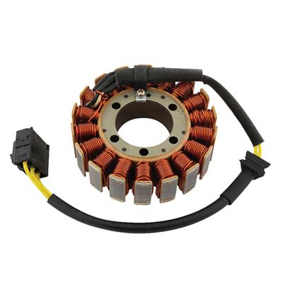 Typical Motorcycle Stator Typical Motorcycle Stator One fun thing about motorcycles is that the charging system (which you would just call "the alternator" on your car) is broken into its two major components, so you can look at them (and repair them) independently. The first part, the Stator (so named, I think, because it STAYS still while magnets spin around it) is simply (usually) three coils of wire that are located very near one or more magnets attached to the engine, so that when it is running, the magnets spin by the coils, inducing an electric current within them. (Yes, Virginia, that is how almost all the electricity you have ever used is made. Coils of wire are passed through a field of magnetic flux, causing the electrons within the wire to get excited and go flying off to some atoms further down the wire that are not quite so excited.) As you can see in this photo, the three coils are artfully arranged so that you would be unlikely to guess that there are three of them, but we know there are three and only three because there are three yellow (typically yellow) wires connected to the lot of them. How that works out will become clearer as we move on... The second part (Have you already forgotten there is a second part? I would have.) is the Regulator. The Regulator, as you might well imagine, regulates the voltage produced by the Stator. Because they are attached to the engine and the engine runs at wildly variable speeds, the magnets induce wildly variable current in the Stator, which is seen as wildly variable voltages on the output connector of the Stator (the three yellow wires). What is worse is that the Stator is producing AC current (alternating current) while your motorcycle, and notably your motorcycle battery, operates on DC current (direct [unidirectional] current). So when we call that second part of the charging system "the Regulator" it is shorthand for what it really is, which is a Rectifier-Regulator. What is a Rectifier? It is something that fixes (rectifies) something else. In this case, the "fix" is that it prevents electricity from flowing backwards. It converts AC current into DC current. In most cases, it is desirable to make use of both the forward and backward energy a Stator provides. When this is done, the circuit that routes Positive and Negative (forward and backward) current flow, so both get sent out in the forward direction, is called a "full-wave" Rectifier. And that is what is being done inside most motorcycle Regulators (a.k.a. Rectifier-Regulators). Just to make matters a little more confusing, when someone says "Rectifier" they may be referring to the entire gizmo that plugs into the bike, or they may be talking about a single-junction semiconductor device with two wires on it. Although the antiquated term for such a device may be "rectifier", for clarity, such a device is usually called a diode. And a module that accomplishes rectification, which is built using a number of diodes, may be called a Rectifier. The schematic symbol for a diode is shown below. The message in the image is very literal. A diode allows current to flow in the direction the arrow (the triangle) is pointing, and the wall (the vertical line) blocks current that might try to come in from the right. If you went out and bought one diode off the shelf, it might look a lot like the cylinder with the white stripe shown below. The white stripe corresponds to the vertical bar in the symbol drawing. It shows where current cannot enter the diode.
The several diodes in a Rectifier-Regulator convert the AC current produced by the Stator into DC current...but by themselves do nothing to make sure that the very high voltages produced by the Stator when the engine is at high RPM, voltages that can exceed 75 volts AC, do not fry the electronics on your bike or fry your "12 volt" battery. That job is handled by the other half of the Rectifier-Regulator (often simply described as "the Regulator"). Exactly how voltage regulation is done is beyond the scope of this post, and it may be done is several different ways, depending on the preferences of the folks who designed the charging system, but in the end, the Regulator will prevent the net DC voltage seen by your battery to be no more than about 15 volts. Typically "charging voltage", the voltage seen across the battery terminals while the engine is at 1500 RPM or more, is going to be around 13.5V to 14.5V DC. That is enough to make sure that current flows INTO the battery, rather than out of the battery (charging, rather than discharging). A good, ordinary lead-acid battery will show about 12.4V to 12.6V DC when it is charged and resting, so hooking a battery to a voltage source that is higher than that will charge the battery.  Typical Motorcycle Charging System A Typical Charging System Schematic This is a circuit diagram of a typical motorcycle charging system. The lines in the drawing are wires and when you see a round dot printed on top of the intersection of two lines, two wires, you know that those two wires are connected to each other. (Line crossings without a dot do not represent an electrical connection.) You can also see six diodes inside the Regulator-Rectifier module. The Stator is show as three coils of wire on the left side of the drawing. One end of each coil is connected to another coil and the loose ends are connected to the diodes in the Regulator. FYI - On many bikes, the three wires that run from the Stator to the Rectifier-Regulator (a.k.a the Regulator) are bright yellow. Notice that each coil of wire in the Stator is connected to a dot between two diodes. Notice that the diodes are all pointed UP, showing that all the current flows toward the positive (+) connection of the battery...and on to other components of the bike via the main fuse and the main power contacts in the ignition switch. Notice that each wire from the Stator is connected between two stacked diodes, so that each pair of diodes does "full-wave rectification" of the current coming from each coil (each "phase") of the Stator. The three coils of the Stator and the three pairs of diodes shown, along with the voltage regulating mechanism depicted by a regulator box and three switches (which are actually some transistors and other stuff) are the essential elements of what is known collectively as a "Three-Phase Charging System". WHEN THINGS GO WRONG There are three main functions in the charging system; production of electrical current by the Stator, rectification of the current by the diodes, and regulation of the voltage by the regulator circuits. Any of these three sections can fail or all of them can fail...and they can fail open (fail by disconnecting) or they can fail short (they can pass current to an unregulated degree or along an unsuitable path).
Testing the Stator coils is very easy. Unplug the Stator from the bike and measure the resistances between the three yellow wires...and between each yellow wire and the frame of the bike. There should be NO current flow from any Stator connection and the bike frame (a.k.a. Ground), and the resistance seen between any two of the three Stator wires should be roughly equivalent...and pretty darn low...probably near 1 ohm. (But whatever DC coil resistance may be, the main concern is that they be about equal, say within 10% - 20% of each other.) If any Stator lead is shorted to ground (to the bike frame) the Stator is bad. If any two Stator leads show a dead short (~zero ohms) or leaks to the bike frame, the Stator is bad. Testing the diodes in the Regulator-Rectifier is more complex conceptually, but not in practice. The Regulator needs to be unplugged from the bike completely. The DC wires (often red and black) and the AC wires (usually three yellow wires) need to be disconnected from the bike's wiring harness. Then each phase can be tested. Sidebar: A Multimeter with a Diode Test Function I use a very nifty multi-meter (that was not at all expensive) with some very useful functions, including Diode Test Mode. Note in these photos that the control knob is set to measure resistance but the meter is reading volts (!). That is because the way a multi-meter always test resistance is to send out a know voltage from inside the meter and then look at what comes back. Diodes have a very particular characteristic compared to other devices like resistors and light bulbs. While resistive devices will show a larger and larger voltage drop across their terminals as voltage is increased, the voltage drop across a diode will stay nearly constant, despite the fact the diode is conducting more and more current flow as the applied voltage increases. In Diode Test mode, the meter reports the voltage drop it is seeing across the device being tested.
Regulator Diode Testing Connect your diode tester to a Stator wire and check for diode current flow through the positive and then the negative terminals of the DC output voltage connector. One of the DC terminals should show current flow...only one. Then reverse your diode tester connections and check the same points. Now the OTHER DC terminal should show diode current flow while the one that flowed before should indicate blocked flow.
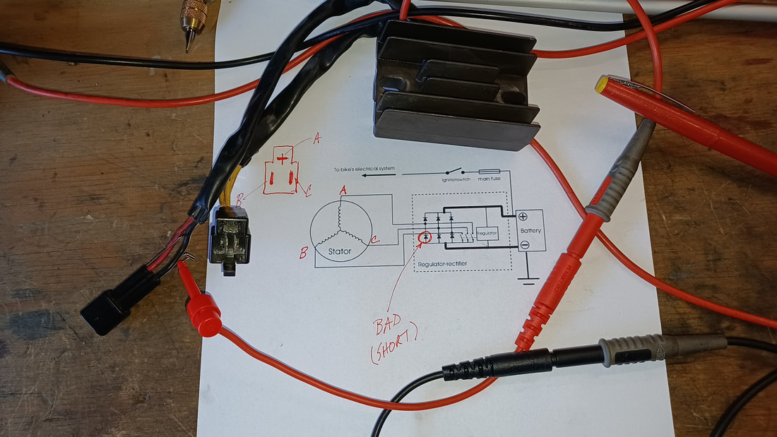 Results from an actual Regulator Assembly Test (which showed one shorted diode) In the example shown here, current was found to be flowing from terminal A on the Stator to the positive (+) DC terminal of the Regulator (which it should) AND to the negative (-) DC terminal of the Regulator (which it should not). That measurement proved that this was a bad regulator. It must be noted that testing the diodes in this manner CANNOT conclusively prove a Regulator is good. Such a test can only prove that a Rectifier part of the Regulator is bad. The diodes could all be just fine and the regulating circuits themselves could be bad, resulting in bad system voltage on the bike. However, in this case, testing revealed at least one bad diode inside the Regulator assembly, so it is a gonner. Additional Tests
Once you have determined the major components of the charging system are functioning with the bike turned off, there are other tests you can do with the bike is running. With the engine running AND the Stator unplugged from the regulator, check AC voltage between each of the three Stator output terminals (Three measurements...on the drawing above would be point A to B, A to C, and B to C). The voltage seen at any given engine RPM should be about the same for each measurement (because the coils and magnets are the same for each phase). You may see nearly 100V AC on these terminals, so be careful. Anything much past 24 volts can be noticeable and 48V and up can hurt...and can certainly be deadly. Watch yourself. This test is particularly useful if the Stator is wounded and only shows a short at higher voltages or only shows an open when it is being vibrated by the motor. The key for each of these measurements is that under the same conditions, they should match each other pretty closely (say +/- 10%). Needless to say, if you see bad results in these tests, you have a bad Stator and need a new one. Repeat the measurement of the AC terminals with the Regulator plugged in. Again, each phase should be the same as another...although probably not the same voltages seen when the Stator was unplugged. Seeing generally lower voltages would be normal because the Stator is doing real work if it is plugged into the Regulator. But be on the lookout for seriously low output voltage on any phase of the Stator. A bad Regulator may collapse the Stator AC output on any or all phases. One low or high phase measurement when the Regulator is plugged in, despite seeing uniform AC voltages on each phase of the Stator when the Regulator us disconnected, suggests a bad Regulator. With the Stator and the Regulator connected normally, check the DC output voltage of the Regulator with the Regulator connected bike. For reference, check battery voltage first and keep that number in mind. Then start the bike and check battery voltage while it is running. Whatever voltage you see at idle should increase somewhat as you increase engine RPM but should stop climbing once it gets into the 14.5V to 15V range. If, when you are at 1500 RPM (high idle), it is not at least equal to the battery voltage you measured when the engine was not running at all, something is wrong (perhaps a bad Regulator, but possibly a bad Battery). If DC voltage keeps climbing past 15V when you increase RPM, STOP THE TEST before you blow bulbs or worse on your bike. And get a new Regulator. Disconnect the DC output of the Regulator from the bike and check Regulator output voltage while the bike is running, again slowly increasing RPM, checking to see how much output voltage increases as engine speed increases. If it is too low to charge your battery (say, less than 12.6V DC) or too high (say over 15V DC), you have a Regulator problem. Just finished a water pump job. Everything is clean and tight. Got the radiator full, topped up the overflow tank, fired her up, watched for coolant flow when the thermostat opened, put the radiator cap on nice and snug, and… 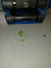 DANG…there is a leak…one stinking, little, slow drip…on the smallest hose in the system. WTF.  There it is. Right under the hose clamp. How is that possible? Well…here’s how. The end of the hose is nice and round and thick…like the rest of the hose. But, uh oh, look at where the clamp has been on the hose. Yep…there’s the hole; right under the lead screw housing. Cutting off the hose end affords an even more telling look. The hose was completely distorted. The flat bottom of the worm drive housing squashed the life out of that poor little hose…squashed a hole right through it.
Oh yea…the smallest hose in the system needed a better small hose clamp; one that does not have a flat spot in the clamping surface like the one on this worm drive hose clamp that had been used on this hose. Here’s one option…a fuel injection hose clamp.
Note how the clamp is designed to deliver clamping force uniformly around a small hose. Make no mistake, even these clamps can be applied in a way that causes a pinch right there under the screw. (Don’t ask me how I know that.) The trick is to get the metal clamp to slide smoothly around the hose as it is being tightened. How? There is a magic rubber dressing that can be used to gigantic advantage every place rubber comes into contact with metal and needs to move, rather than stick. It is awesome for sliding stubborn hoses onto or off of water pump or radiator fittings, it is the bomb for demounting and mounting tires (that’s right…dump the soapy water…this stuff will change your life), it is the coolest for slipping wires through jackets. What is this magic stuff? It is already on your work bench; plain old WD-40. That’s right. It works miracles on rubber when you need to get it to slide past some metal…and then it evaporates away, leaving newly mounted tires or hoses or hose clamps, clean, dry, and ready to go to work. So, yea, this is a twofer. First, you learned NOT to use ordinary worm drive hose clamps on any hose where the flat spot in the worm drive mechanism represents a significant portion of the circumferences of the hose to be clamped (i.e. a too small hose). If you do, you risk putting a flat spot in your hose…and causing a leak. Second, you learned that, when it comes to fitting rubber parts, WD-40 is your best friend. 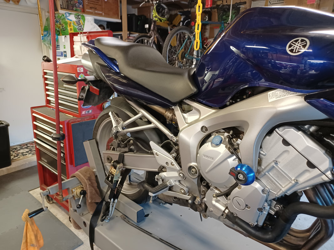 Backwards? Well, yes. Normally it is the front wheel that goes into the wheel vice at the front of the lift. Why not this one? Because this bike needs a new front tire. The front end needs to come up off the ground, not the back tire, to service this bike...but that is not the whole answer. A bike lift (a.k.a. a lift table) allows a mechanic to work on a bike without crawling around on the floor. If you work on a lot of bikes or are not 20-something anymore, a bike lift is a godsend. But sometimes, the bike needs to be lifted up from the lift table...the wheels need to be in the air, perhaps, as in this case, to remove a wheel and change a tire. What is a mechanic to do? The easy traditional answer is a small scissor jack, like the one shown in these photos:
The scissor jack is the little blue gizmo sitting between these two bikes and the lift table surface. Capable of lifting 1000 lbs., it is very handy item to have. But there is a catch. The bike you want to lift has got to have some solid structure on the bottom for the jack to contact that can bear the weight of the bike as the jack lifts it off one or both of the wheels. In the first photo, the rear wheel of an old Goldwing is being lifted while the front wheel is clamped in the wheel vice. It should be noted that this allows the bike to rotate (however slightly) about the front axle, without stressing any of the frame elements. In the second photo, the front wheel of a VTX is being lifted, while the rear wheel is strapped down to the table with the two orange "Y" straps shown and a matching pair out of view on the other side of the wheel. This allows the bike to rotate around the rear axle, without stressing any frame elements, yet, as in the first photo, the bike is being securely held upright, even as a wheel lifts off the table surface. But I digress. The central story here is the handy little blue scissor jack...and why it couldn't be used this time. 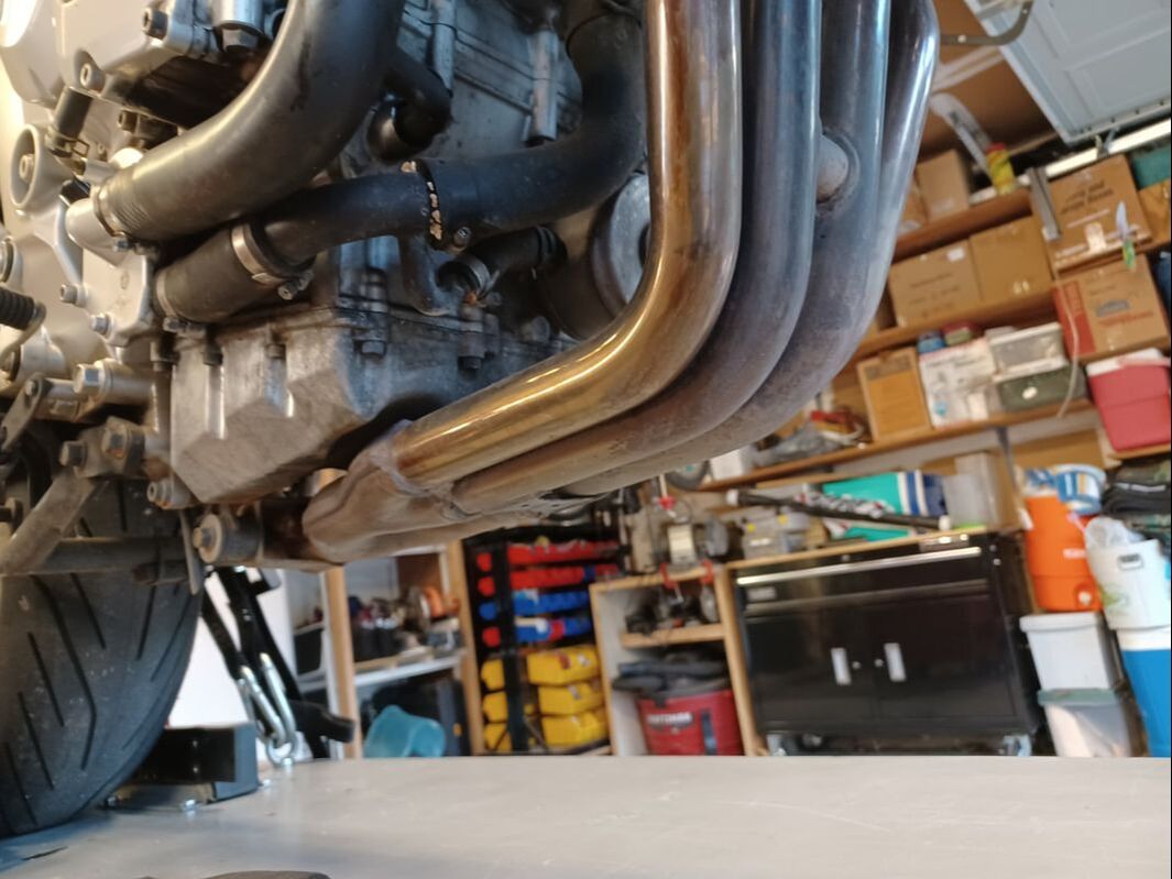 Here's the bottom side of the FZ6. No solid structure down there; nothing but exhaust pipes. Lots of bikes are like this...particularly sport bikes. Do not be the poor fool who lifts his bike by putting a jack under the pipes. You will not like the results. Sure, if we wanted to lift the rear wheel, we might get a jack to contact something near the back, like the pivots for the center stand...but to lift the front, the lift point needs to be in front of the bike's center of gravity...and that looks like a problem. Fortunately, somebody has solved that problem. We can use a "Head Stand". 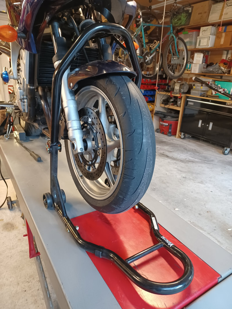 Even if you hated High School Geometry, you are going to love a Head Stand. A Head Stand us a wonder of geometry and the power of leverage. The stand has hinged uprights, a lifting pin at one end, the lever end (the hoop handle shown), and wheels that allow the whole affair to pivot as the hoop handle is pressed downwards. As the handle goes down, the wheels roll forward and the pin is lifted upwards as the uprights go from folded, to straight and locked (as shown here). It takes a little effort, but not so much that even a skinny mechanic would find difficult. 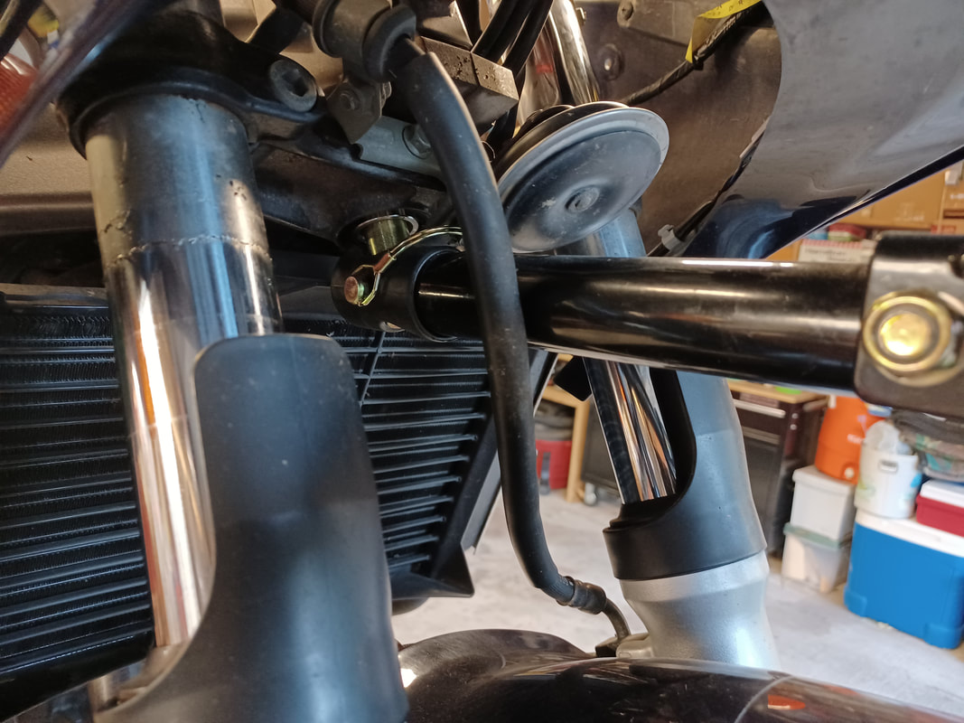 The pin, as shown here, goes into the hole found at the bottom of the steering head on almost every bike. Those holes come in a variety of sizes, so if you plan to work on lots of different bikes, you get a bunch of different pins, not a bunch of different stands. The steering head is always located above the bike's center of gravity, so a bike will always hang securely from the lift pin, without any danger of the bike flipping over after it is lifted.
The downsides of using a Head Stand are:
However, since the front wheel will still pivot left to right, obstruction caused by the stand legs can mostly be avoided. Not having the ideal lift height is more problematic, which is to say, can usually be addressed with a little more effort and innovation (e.g. you may need to do a little more disassembly than would have otherwise been required to get additional clearance, or you may need to slip something under the lifted wheel to reduce excessive clearance). One word of caution: Head Stands should not be used alone...that is without some sort of REAR stand or clamp. You might get away with using only the front stand, but you might not, and having a bike topple over just isn't fun. Use a rear stand or a wheel vice or some other sort of rear wheel tie-down to make sure the bike stays upright while it is being lifted. Yes, I know I said earlier that the bike's center of gravity is below the steering head...but it may not be far below, and if that is the case, removing the front wheel or the bike being jostled side to side might result in a tumble. So...play it safe. Secure the rear wheel before you lift the front. Bottom line, Head Stands are a very useful and inexpensive tool...and one of very few reasonable ways to lift the front end of some bikes. If you need one, get one. You won't regret it. 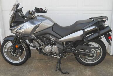 A very pretty 2009 Suzuki V Strom 650 came into the shop last week. She looked showroom fresh, with less than 2k miles on her. Needless to say, she had been parked for years...and sadly, with a half full tank of gas...which, predictably, turned into a tank full of rust.
The owner had already cleaned the tank and replaced some or all of the fuel pump assembly, which lives inside the tank itself, but despite these ministrations, she would bog down under load. She idled like a champ, but just wouldn't pull when the rider cranked on the throttle. Very frustrating for the owner. There are a number of esoteric possible causes for that behavior, but the most obvious thing to check is fuel pressure, which is a proxy for looking at fuel flow. This is a fuel injected bike, so fuel pressure is supposed to be pretty high, around 60 PSI. Fuel injectors just won't work right if the pressure gets too low. And if the fuel pump assembly cannot keep up with the fuel demand from the engine (as the engine control computer tries to get it to make more power), then the fuel pressure in the fuel supply line is going to drop. Because spraying 60 PSI gas around your shop is a bad idea, selecting the right fuel pressure test rig is important. Fortunately, bike manufacturers have largely selected standardized fuel line fittings when they design their bikes. In this case one of the mid-size quick disconnect fittings was just the ticket and that allowed disconnecting the fuel line from the tank, plugging in the tester T-connector, reconnecting the fuel line to the Tee and then hooking up the pressure gauge to the open end of the Tee. The results can be seen at the links below... Start and Blip Throttle and Advance to Higher RPM What you see here is a significant drop in fuel pressure as engine RPM is increased...despite the fact that the bike is just sitting in the shop in neutral, not even spinning the back tire. So even with zero load on the engine, the fuel pressure drops...a lot. You might even notice in the second video that you can hear the RPM begin to drop (despite increasing throttle) when fuel pressure gets near 20 PSI. It is significant that the pressure drop is smooth. Pressure rolls off steadily as RPM increases. It does not, for example, spike low intermittently and then pop back, which might suggest an intermittent electrical connection to the (electric) fuel pump. Nope, this sure looks like plain old low flow. The fuel pump assembly just cannot keep up. Now why say "fuel pump assembly" and not "fuel pump"? Because inside the tank there is not only a fuel screen / filter, there is also a pressure regulator, as well as the pump itself. Poor flow could be caused by problems with any one of them, not to mention the possibility that the fuel pump assembly components themselves may have been misassembled and are leaking fuel from the pressurized lines inside the tank into the low pressure area inside the tank itself. That would not produce a fuel leak that is visible outside the tank, but it could cause a pressure drop in the fuel line when fuel demand increases. So, how did this all turn out? We don't know yet. Now that he has a solid answer on the fuel pressure question, he and his bike are back home awaiting the arrival of a new Suzuki OEM Fuel Pump assembly, which he will install after taking another good look inside that tank...to see if another cleanup is in order before installing the new pump. Stay tuned! What does every mechanic want most? New wrench set? A better set of screwdrivers? Nope. In the middle of just about every job, at some point we say "Damn, I need one more hand!" 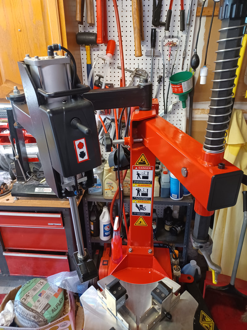 Well, when it comes to changing tires, it couldn't happen more often. Fortunately, some bright guy came up with a way to add and extra "hand" and a very strong arm, to a tire changer.
The need is pretty simple. To demount or mount a tire, the sidewall needs to be pushed towards the center of the wheel. Some tires make that VERY difficult, particularly, low profile, high performance tires...the sort you might find on large, powerful bikes. With the advent of "helper arms" on tire changers, jobs that are very difficult with conventional tools become far easier...if not downright easy. The helper arm, the black mechanism shown above, swings an air ram that is attached to a plastic foot, over a wheel and tire that has been clamped to the turntable. With the press of an air valve, the ram presses the foot down onto the sidewall as far as necessary to put the bead into the "drop zone" (the smaller diameter inner section of the wheel) which now gives enough clearance for the tire to be shifted sideways on the wheel, allowing the bead to be lifted over (demount) or pressed past (mount) the opposite side of the wheel. The arm is double jointed and the foot pivots, allowing the air ram to maintain pressure on the tire, even as the wheel is rotated on the turntable. Pretty nifty. CLICK HERE to see it in action! |
Categories
All
Archives
January 2024
|
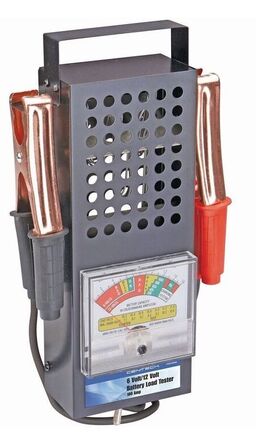

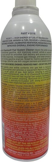
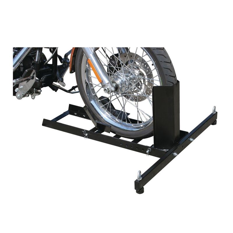
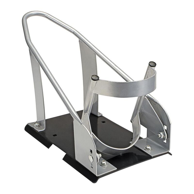
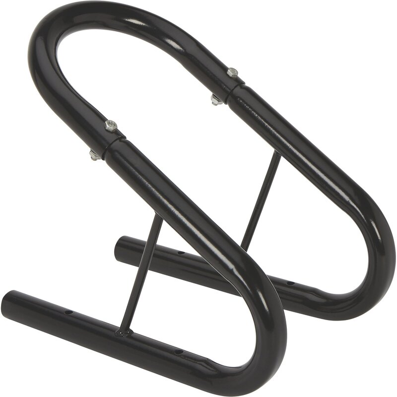
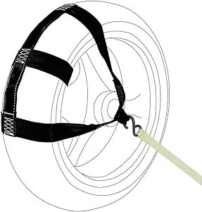
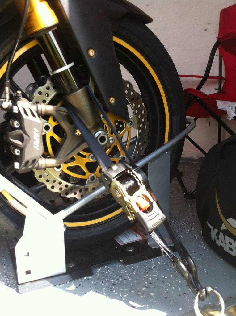
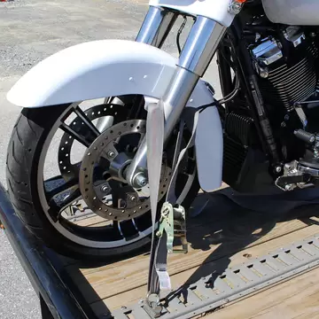
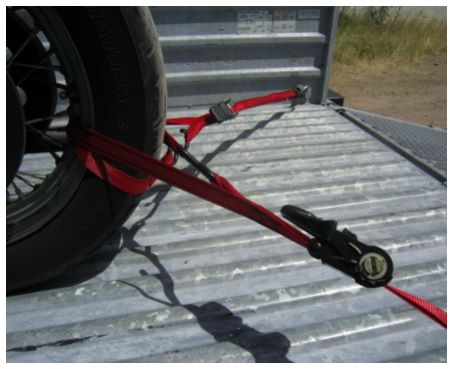
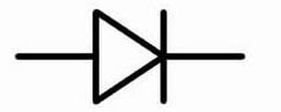
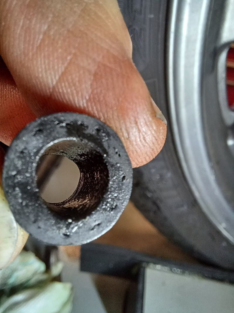
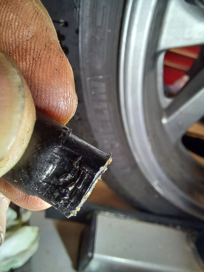
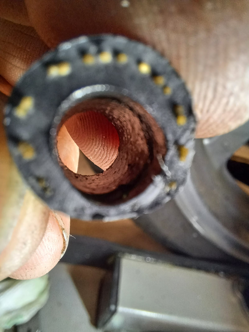
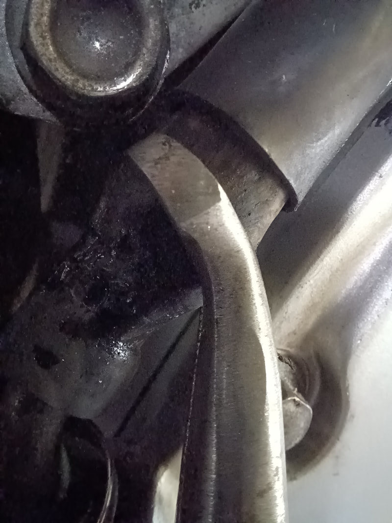
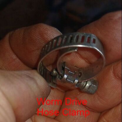
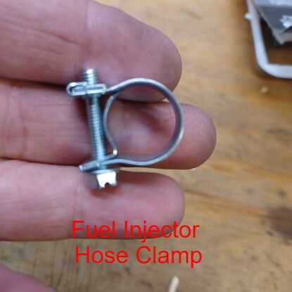
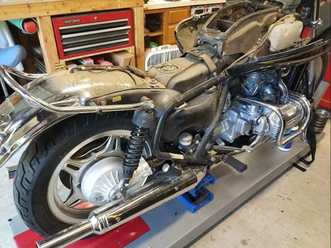
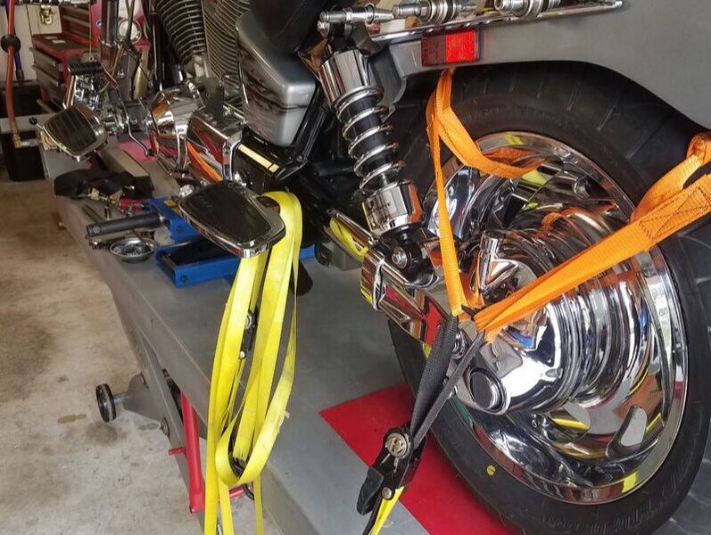
 RSS Feed
|
© WrenchMonster 2018
|
WrenchMonster™ is a Division of DemonLite, LLC.
|